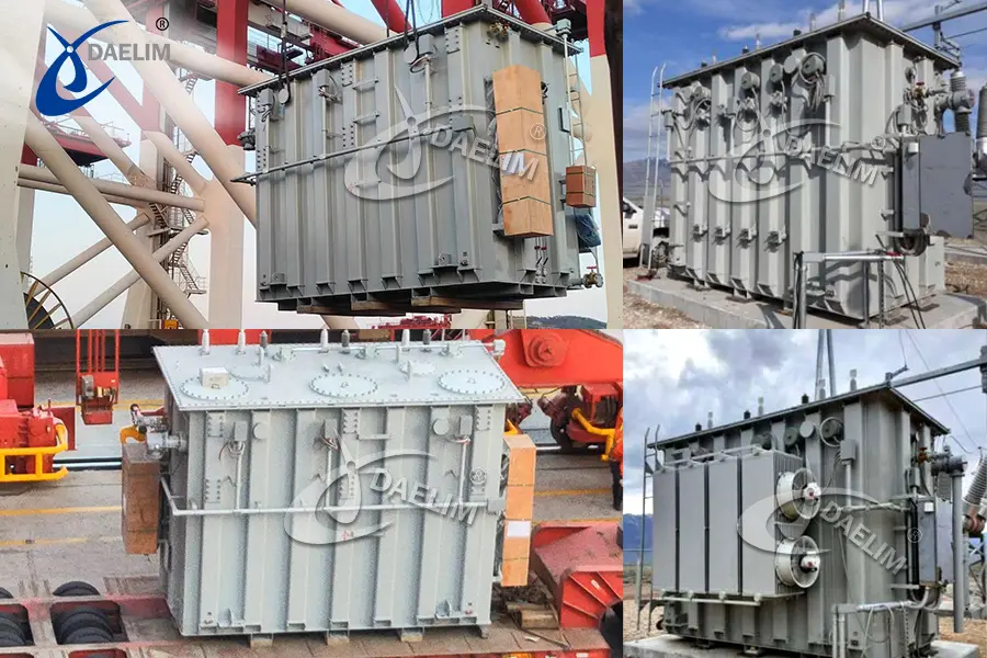
Basic introduction of electric furnace transformer
Since the Second Industrial Revolution, electricity has become the energy of industry, and human beings have entered the "electric age". Power transformer is a important part of our heavy industry, power transformer will transfer the high voltage from the power transmission system, to low voltage for the electrical equipments in our industry.
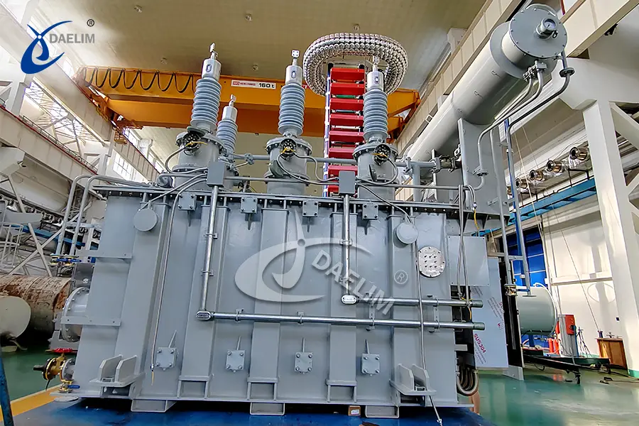
Furnace transformer is one type of oil immersed power transformers, they are used for furances' power supply. So what is a furnace transformer? Compared with other transformers, is there any particularity in electric furnace transformers? Check out today’s article and find out the answers.
What is furnace transformer?
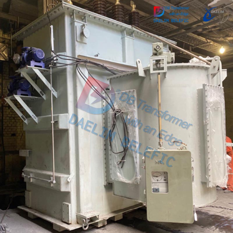
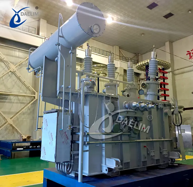
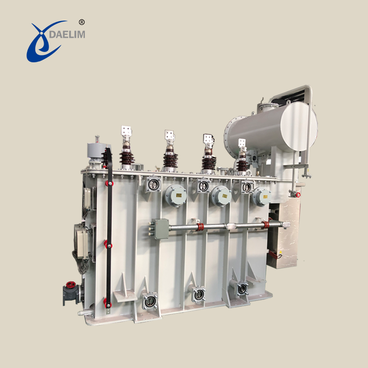
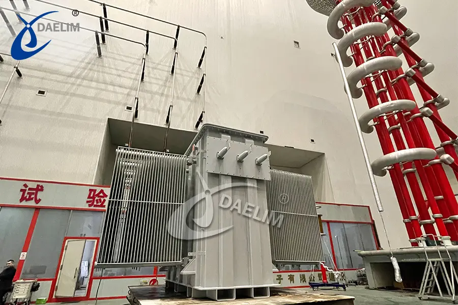
The electric furnace transformer, also known as the smelting transformer, is a special power transformer mainly used for smelting metals such as steel. It can withstand ultra-large current loads and endure repeated high mechanical and thermal stresses caused by electric arcs. Typically, the primary voltage of the electric furnace transformer does not exceed 72.5 kV. The transformer can handle currents ranging from several thousand to tens of thousands of amperes. Generally, it has a large capacity and comes in two designs: split type and integrated type. The electric furnace transformer uses carbon rods as electrodes and is commonly employed in the electric furnace smelting of special steel, white corundum, electrolytic aluminum, and other materials.
Design Features of Electric Furnace Transformers
Electric furnace transformers are designed to handle the high currents and variable voltages required for electric furnaces. Key design features include:
Voltage Taps and Core Design
Electric furnace transformers typically include multiple taps to adjust the secondary voltage. Due to the high current and few effective turns in the low-voltage winding, taps are often set in the high-voltage winding. The high-voltage winding requires more turns to provide the necessary voltage range at the secondary.
The core flux density varies with each tap due to different primary turns for each secondary voltage. The largest secondary voltage determines the core size, while the smallest secondary voltage influences the total number of primary turns. Consequently, the secondary voltage range significantly impacts the transformer’s weight and cost.
Reactance Characteristics
The range of secondary voltage affects the reactance of the transformer. In a well-designed transformer, the reactance should vary inversely with the square of the secondary voltage. Typically, the reactance should not exceed 15%. A larger tap range may complicate the coil arrangement, while a smaller tap range results in a more compact transformer.
Coil Arrangement
Coils should be arranged to ensure that the primary tap positions equally affect the reactance of each multi-coil in the low-voltage winding. A common approach is to wind each high-voltage coil fully and connect all coils in parallel in multiple groups. Taps are taken from the center of each winding, and corresponding taps are connected in multiple ways and switched quickly by a voltage regulator.
Transformer Construction
The transformer tank, cover, and coil clamping structures are generally made of steel. Given the high current requirements, care must be taken in arranging busbars and leads to avoid loss concentration and heating of surrounding magnetic materials due to leakage flux. Busbars should be subdivided according to coil arrangement and staggered to ensure opposing current polarities in adjacent busbars.
Three-Phase Connections
Most large arc furnaces use a three-phase power supply, and it is common practice to employ a three-phase transformer with a delta connection for the low-voltage winding. Traditionally, a delta connection inside the transformer was used, but this often led to excessive losses. Nowadays, staggered busbars are passed through the transformer cover, and the delta connection is outside the transformer. Suppose the distance to the electric furnace is significant. In that case, busbars should be placed close to the furnace after leaving the transformer to minimize losses and avoid heating of nearby magnetic materials.
Cooling Systems
Water-cooled transformers are preferred for large electric furnaces due to cost and space savings, and because there is often an ample supply of cooling water available for both the furnace electrode rack and the transformer. If the water quality is questionable, naturally cooled transformers are used instead.
Dust Protection
Electric furnace transformers are often installed in dusty environments. To prevent dust ingress, transformers must be well-sealed. Properly designed stuffing boxes around each busbar can effectively prevent debris from entering the transformer.
Reactance Requirements
A key characteristic of arc furnaces is that the arc resistance decreases as the current increases, which can cause instability unless a sufficient constant impedance is connected in series with the supply voltage. For large arc furnaces, the inherent reactance of the transformer is usually adequate. For smaller arc furnaces, additional reactance may be necessary, either by designing the transformer with higher reactance or by adding a separate reactor in series. The transformer’s inherent reactance should not exceed 10% to 15%, and this value is fixed once selected. If a separate reactor is used, it should include taps to allow for adjustment of reactance as needed.
What are the furnace transformer's basic specification?
(1) Primary rated voltage. This voltage is the voltage applied by the power supply network to the primary coil of the transformer, that is, the standard voltage of the power supply network, mainly including 6kV, 10kV, 20kV, 35kV, and 110kV.
(2) Secondary voltage. The secondary voltage is also known as the low-side voltage. Its size and its series mainly depend on the requirements of the steelmaking process, and its range is generally between 100 and 1200V.
(3) Rated current. No matter how the transformer is connected, the rated current in the low-voltage side coil remains unchanged; while the current in the high-voltage coil changes with the change of the secondary current.
(4) Rated capacity. The capacity at the highest secondary voltage is defined as the rated capacity of the electric arc furnace transformer.
(5) Power supply frequency. In China, the power frequency f=50Hz, but in other countries, the regulations of the power frequency are different based on local electrical system.
(6) The connection line and connection group of the coil. When the coils are connected in a Y-△ shape or a △-△ shape, the connection group label is Yd11 (11 means the primary and secondary phase angles differ by 11°) or Dd0 (0 means the primary and secondary phase angles differ by 0°).
(7) Efficiency. Generally, η = 95% to 98% for small and medium-sized transformers, and η = 99% for large transformers.

What are the types of electric furnace transformers?
(1)Resistance Furnace Transformer
Mechanical parts can be heated in resistance furnaces and salt bath furnaces for heat treatment, powder metallurgy sintering, non-ferrous metal smelting, etc. To reduce and adjust the input voltage of the electric furnace, a resistance furnace transformer needs to be equipped between the furnace and the power grid because the resistance of the heating element is too small or changes too much during the heating process.
Low-voltage, small-capacity and salt-bath furnace transformers are usually dry-type transformers with box shells and natural cooling; resistance furnace transformers with medium capacity (hundreds to thousands of VA) are usually oil-immersed, self-cooling transformers; large-capacity transformers are forced oil circulation water-cooled.
(2)Electric arc furnace transformer
Special transformers used to power electric arc furnaces for steel smelting. These transformers are large, complex and have high technical requirements. The secondary side voltage is low, generally between tens and hundreds of volts, and it must be regulated within a wide range; the secondary side current typically reaches thousands to tens of thousands of amps. The melting period in iron and steel smelting also requires high power, and the transformer must have a 20% overload capacity within 2 hours. The primary side of an electric arc furnace transformer should be connected to a current limiting reactor or should have a large impedance to limit short circuit current in the process of steelmaking since the collapse of the charge is likely to cause electrode short circuit.
To operate the electric furnace, the power supply transformer must also be able to adjust the voltage. The voltage can be adjusted in two ways.
① Direct voltage regulation: the tap is connected to the tap changer on the primary winding of the transformer. A *-Y switchover can also be used between the three phases of the primary side to regulate the voltage on the secondary side. The *-Y switching technique is a very efficient way of regulating voltage, which can reduce the secondary voltage to 1/ of the original without changing the number of turns on the primary side. The 9 taps on each phase winding plus the *-Y switching give a total of 18 levels of voltage.
② Indirect voltage regulation method: indirect voltage regulation method with series transformer. This main transformer has three windings (see multi-winding transformer), winding 1 is a high-voltage winding connected to the grid, winding 2 is a winding with a tap connected to the primary winding 4 of the series transformer II through a tap changer, and winding 3 is connected to the secondary winding 5 of the series transformer II to provide power to the electric furnace load. Through the tap changer, the output voltage of windings 3 and 5 can be changed by changing the primary voltage of series transformer II. Usually, the 3 and 5 windings connected to the load are 1 to 2 turns and made from a figure-8 coil of copper or aluminum plate.
(3)Shell furnace transformer
Structural features:
① Iron core
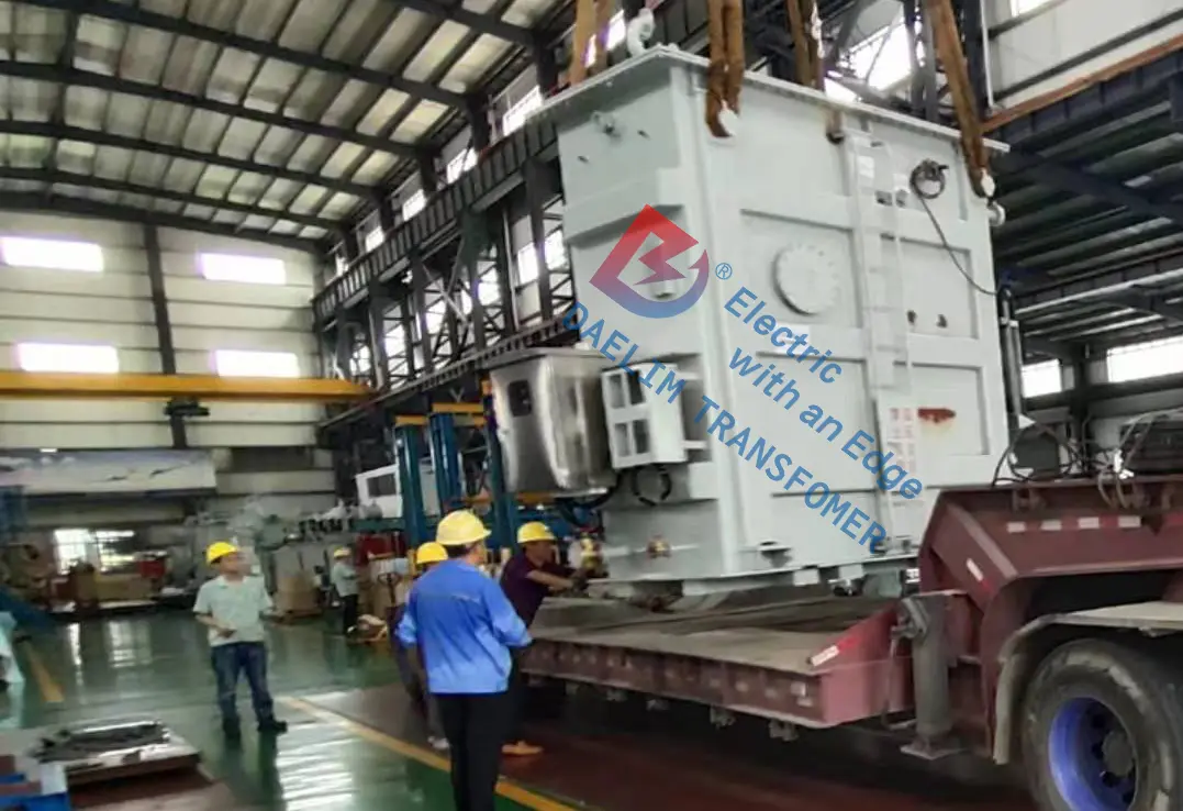
The iron core of the shell-type electric furnace transformer is a frame structure with full miter joints. The core width is narrow, the heat dissipation condition is good, and the structure is simple.
② Winding
The winding of the shell-type electric furnace transformer is a rectangle with the same cross-sectional shape as the stem. The low-voltage winding is made of a single piece of copper plate, with good heat dissipation conditions, and the head is a welded structure; the high-voltage winding is a pie structure. The winding arrangement shall be staggered. The high-voltage line segment and the low-voltage line segment in each group should have the same magnetic potential, and their radial dimensions should be basically the same. Theoretically, the low-voltage line segments are placed at both ends, because the insulation distance to the iron core is small. However, in order to make the short-circuit impedance of the transformer smaller, multiple magnetic flux leakage groups are required to meet the requirements, and placing the low-voltage line segments at both ends will limit the number of magnetic flux leakage groups, so sometimes the high-voltage line segments are placed at both ends. In the process of voltage regulation, in order to make the line segment configuration symmetrical and ensure the balance of the magnetic potential, the voltage regulation line segment usually adopts multiple parallel connections, so as to ensure that the impedance of each leakage flux group is equal, and the current of each low-voltage line segment is also equal.
③ Cooling method
Shell furnace transformers generally use forced oil-guided circulation, forced water cooling, forced oil-guided circulation, and forced air cooling. Since the shell-type transformer can conveniently set a partition between the oil tank and the body, the cooled transformer oil is forced to flow through the wire cake, the oil flow is uniform, the temperature difference of each part is small, the heat dissipation effect is good, and the temperature of the hottest spot can be reduced. Decrease it by about 5°C to increase the extra overload capacity of the transformer.
④ Fuel tank
Since the winding of the shell-type transformer is completely shielded by the iron core, it is less likely to be damaged by external force, so a suitable shape oil tank can be used according to the shape of the body, thereby greatly reducing the size and weight of the transformer.
Advantage:
① Small mechanical force and good strength
Theoretical calculations show that the radial electromagnetic force of the shell-type transformer is very small. Although the axial electromagnetic force is relatively large, it can also be significantly reduced when there are many leakage magnetic groups. The windings of the shell-type transformer are completely surrounded by insulating parts, and the iron core surrounds them. The short-circuit force is directly transmitted to the fuel tank through the insulating parts and the iron core, unlike the core-type structure with less winding support surface, so the shell-type transformer has high mechanical strength.
② Strong impact resistance of the winding
Because the shell-type transformer winding has few coils and large radial size, the capacitance between the coils is large, but the capacitance to ground is small, so when the impulse voltage acts on the shell-type transformer, the initial voltage is basically linear. distribution, the voltage gradient is greatly reduced. At the same time, due to the large inherent capacitance of the shell-type transformer, the oscillation time of the winding voltage is prolonged, and the transient voltage has been attenuated before the winding reaches the amplitude. Therefore, the shell-type transformer winding has a good performance of withstand overvoltage shock.
③ Low impedance
Each phase of the shell-type transformer can be divided into several leakage magnetic groups, and the radial size of the wire cake is large, the impedance can be designed to be 2% to 3%, and the mechanical force and load loss are also small. Since the reactive power of the transformer is greatly reduced, the power factor of the electric furnace naturally increases.
④ Split-phase voltage regulation has no effect on the magnetic circuit
Due to the asymmetry of the three-phase magnetic flux of the split-phase voltage regulation, the core-type transformer must use a five-column iron core. But in the shell-type transformer core, each phase already has an independent magnetic circuit, and the asymmetry of the magnetic circuit does not affect the design of the core.
⑤ Short leads and easy impedance balance
The wire end outlet and the branch wire are drawn as short as possible at the upper part of the winding, and the low voltage winding outlet can be of the same length, thereby eliminating the impedance imbalance of the low voltage lead and reducing the power transfer during the operation of the electric furnace.
⑥ Low loss

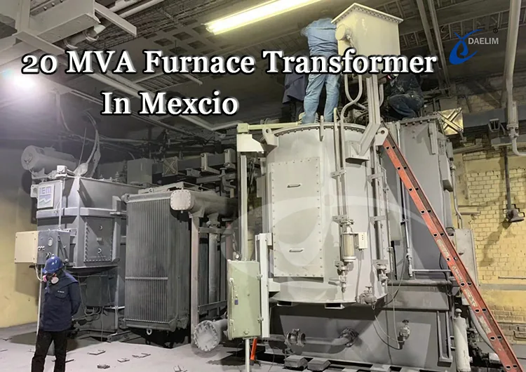
Daelim Transformer’s furnace transformers are exported to Mexico, Argentina, and other countries. Our team excels in the design and technical requirements of furnace transformers and brings extensive experience to every project. If you’re seeking a reliable supplier of furnace transformers, don’t hesitate to contact us today!
Daelim also produce substation power transformer, pad-mounted transformer, HV power transformer, etc... With different internatioanl standards and certifications, Daelim will be your trusted transformer supplier.
Related Products
Related Article
GIS Mobile Substation Project , Ecuador
Built in 2015, this GIS was built in a power plant in Ecuador. The high-voltage components are filled with SF6 gas as insulation and arc extinguishing medium. The main function is to protect, measure and dispatch the power system.
20mVA Furnace Transformer, Mexico
Installation in 2018, is used to supply power to an electric furnace, which lowers the high voltage to the furnace-required lower voltage. It was designed according to client's request.
13.8 kV 10.5 MVA Substation Transformer for Ecuador
A customer from Ecuador contacted Daelim Transformer for a 10.5MVA substation transformer (13.8kV high voltage, 2.4kV low voltage). Daelim Transformer provided a customized solution, conducted virtual factory tours, ensured rigorous quality control via video inspections, and offered post-delivery online training and ongoing support, fostering a successful partnership.
20MVA Power Transformer for the United States
This project involves the development of a 20 MVA three-phase power transformer tailored for the United States market. The primary voltage is 24.94kV, and the secondary voltage is 4.16kV, indicating it functions as a step-down transformer. The design and production fully comply with IEEE C57.12.00 standards and have passed third-party UL team testing. All accessories also adhere to IEEE standards. FR3 vegetable oil serves as the insulating liquid for the transformers.
230 kV Three Phase Power Transformer For USA Market
In 2023, Daelim Transformer designed and manufactured a cutting-edge 230 kV three-phase power transformer for a client in Nevada, USA. The client recently shared installation and operational photos, showcasing the successful deployment of this remarkable transformer. Let's delve into the specifics of this transformer project!
Canadian 69 kV Substation Transformer Project
Today, we are excited to present a case study on a 69 kV substation transformer project by Daelim Transformer. Our Canadian client required a step-down transformer for their substation to connect with the hydroelectric grid in Quebec.

