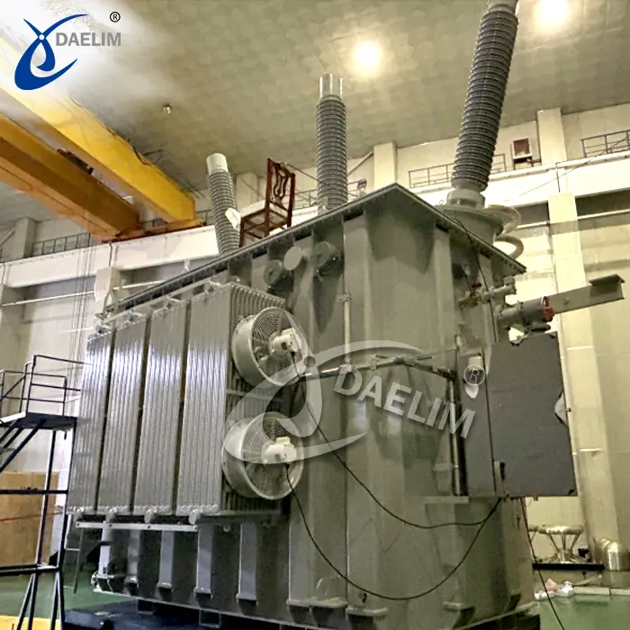
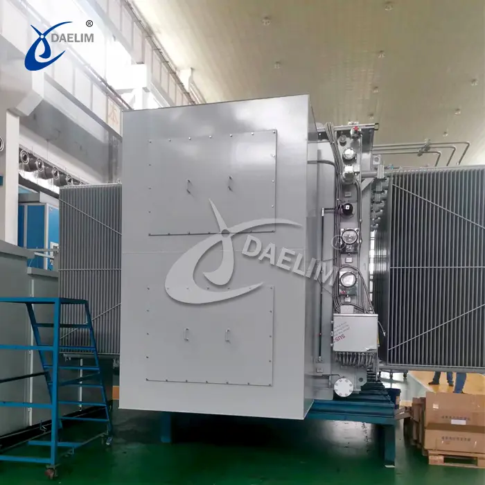
What are the maintenance points for transformer operation?
Allowable Temperature
During transformer operation, copper and iron losses in the coils and cores generate heat, raising the temperature of these components. Excessive temperatures can lead to insulation aging and loss of mechanical elasticity. The temperature varies across different parts of the transformer, with the coil temperature being the highest, followed by the core, and the insulating oil. The upper oil temperature is higher than the lower oil temperature. For Class A insulation transformers, the winding temperature should not exceed 105°C when the ambient temperature is 40°C. Consequently, the maximum oil temperature should not exceed 95°C to prevent oil quality deterioration. Generally, the upper oil temperature should remain below 85°C to avoid excessive oxidation of the insulating oil. For transformers with forced oil circulation, water cooling, and air cooling, the maximum oil temperature should not exceed 75°C.
Allowable Temperature Rise Monitoring the upper oil temperature alone is insufficient for ensuring safe transformer operation. It is also essential to monitor the temperature rise, which is the difference between the transformer's temperature and the ambient air temperature. For Class A insulation transformers, the national standard specifies a winding temperature rise of 65°C and a maximum oil temperature rise of 55°C when the ambient temperature is 40°C. As long as the temperature rise remains within these limits, the transformer can operate safely within its specified service life under rated load.
Reasonable Capacity
Under normal operation, the power load on the transformer should be between 75-90% of its rated capacity.
Voltage Regulation
The maximum unbalanced current on the transformer's low voltage side should not exceed 25% of the rated value. The allowable variation range of the supply voltage is ±5% of the rated voltage. If the voltage deviates from this range, it should be adjusted using a tap changer to bring it within the specified range (adjustment should be done with the power supply off). Voltage adjustments are typically made by changing the position of the primary winding tap. The tap changer adjusts the transformation ratio by altering the number of turns in the high-voltage winding. Low voltage does not affect the transformer but reduces output, impacting electrical equipment. High voltage increases magnetic flux, saturating the core, increasing core losses, and raising transformer temperature.
Overload Management
Overload conditions are categorized as normal and accidental. Normal overload, caused by increased power consumption, raises transformer temperature, accelerating insulation aging and reducing service life, thus generally not permitted. However, transformers can temporarily handle short-term overloads under special circumstances, not exceeding 30% of the rated load in winter and 15% in summer, as per the transformer's temperature rise and manufacturer guidelines. Accidental overload occurs during power system or substation faults to ensure continuous power supply to critical equipment. Though this condition raises the coil temperature beyond allowable limits and accelerates insulation aging, its likelihood is minimal. Accident overload durations and multiples should follow manufacturer regulations.
These maintenance points ensure the safe, reliable, and efficient operation of transformers, minimizing the risk of faults and extending their service life.
Related Products
Related Article
Transforming Global Energy Infrastructure with Large Transformers
Large transformers crucial for global electricity transmission. China leads in eco-friendly, advanced tech. Daelim Transformer excels globally with high-performance units, expanding in North America, meeting rising demand.
Causes and Measures for Abnormal Transformer Temperature
Abnormal transformer temperature can result from internal faults, unopened radiator doors, blocked or leaking respirators, poor transformer structure, and cooling device malfunctions. Measures include identifying faults, opening doors, clearing respirators, installing magnetic isolation, and ensuring cooling device functionality.
Requirements for Transformer Core Grounding Points
Transformer cores must have a single grounding point to prevent floating potentials, short-circuit currents, and overheating. Improper grounding can cause insulation damage, increased iron loss, gas generation, and power interruptions, compromising transformer and grid safety.
Manifestation Characteristics of Transformer Core Grounding Fault
Transformer core grounding faults cause overheating, gas production, and insulation damage. Symptoms include increased hydrocarbons in oil analysis, high grounding current, and visible core burns or discharge marks. Accurate diagnosis requires comprehensive testing, electrical measurements, and visual inspections.
Prevention and Treatment Measures for Transformer Core Grounding Faults
Prevent transformer core grounding faults by ensuring proper insulation, regular current measurements, and chromatographic analysis. Address faults with temporary measures, inspections, and targeted repairs. Emphasize design and manufacturing standards to prevent faults and ensure safe operation.
Measures to Prevent Transformer Short-Circuit Accidents
Enhance transformer resilience against short circuits by optimizing design, strengthening insulation, improving maintenance, and upgrading protection systems to ensure reliable grid operation and minimize downtime.

