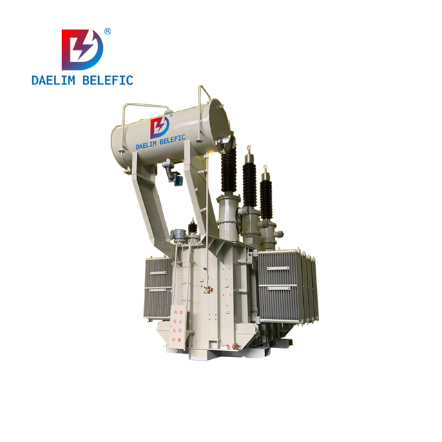
What is the difference between rectifier transformer and power transformer?
What is a Rectifier Transformer?
Current conversion encompasses three working modes: rectification, inversion, and frequency conversion. Rectification is the most widely used. The primary characteristic of a rectifier device is that it converts input AC power into output DC power through rectification and filtering. A rectifier transformer is the power transformer used in rectifier devices. Most industrial rectified DC power supplies are obtained through rectifier transformers and rectifier devices.
What is a Power Transformer?
Power transformers typically refer to transformers that supply power to electrical drive systems. Most transformers in power grids are power transformers.
Differences Between Rectifier Transformers and Power Transformers
Functional Differences
-
Functions of Rectifier Transformers:
-
Provide appropriate voltage for the rectifier system.
-
Reduce the pollution of the power grid by the waveform distortion caused by the rectifier system.
-
The output of a rectifier transformer is still AC, solely supplying power to the rectifier device. Typically, the primary side is connected in a star configuration, and the secondary side is connected in a delta configuration to suppress higher-order harmonics. The corner neutral point of the secondary side is not grounded. When the rectifier device is grounded at one point, it does not cause equipment damage, and a ground fault alarm signal is sent through the ground detection device. Additionally, shielding isolation is added between secondary coils.
Rectifier transformers are mainly used in electrolysis, smelting, excitation, power transmission, series speed regulation, electrostatic dust removal, and high-frequency welding. Structurally, they are somewhat different. To achieve smooth waveforms, some electrolysis rectifier transformers are made with six-phase outputs, and an external six-phase rectifier bridge is added to obtain relatively smooth waveforms. According to the current waveform characteristics and anti-harmonic requirements of the thyristor rectifier circuit used in smelting and high-frequency welding, the eddy current loss in the windings and stray loss in the structural components of the rectifier transformer are optimized for specific data and processes. In fact, the overall structure is also similar.
Power transformers are usually grounded at the neutral point in a y/y connection (providing single-phase power). If used for rectifier equipment, they can damage the rectifier equipment in the event of a ground fault and have poor suppression of the higher-order harmonics generated by the rectifier equipment.
Different Uses
Transformers used as rectifier power supplies are called rectifier transformers. Most industrial rectified DC power supplies are obtained from the AC power grid through rectifier devices composed of rectifier transformers and rectifiers. In today's highly modernized society, their extensive use can be seen directly or indirectly in almost every field. Power transformers are mainly used in power systems, daily lighting, and factory electricity. The main uses of rectifier transformers are as follows:
-
Electrochemical industry.
-
DC power supply for traction.
-
DC power supply for transmission.
-
DC power supply for DC transmission.
-
DC power supply for electroplating or electrical processing.
-
DC power supply for excitation.
-
DC power supply for charging.
-
DC power supply for electrostatic precipitators.
Output Voltage Differences
-
Naming Differences: Due to their close association with rectifiers, the output voltage of a rectifier transformer is called the valve side voltage, named after the unidirectional conductivity of the diode.
-
Calculation Method Differences: Due to the different waveform of the rectifier load current, the calculation method for its output current differs significantly from that of power transformers and varies for different rectifier circuits.
Differences in Design and Manufacturing
Due to the different applications of rectifier transformers and power transformers, their design and manufacturing also differ significantly:
-
Considering the working conditions of rectifier transformers, they achieve low current density and magnetic flux density, as well as slightly higher impedance.
-
In terms of winding structure, the valve side sometimes requires two windings to supply power for forward and reverse transmission or forward transmission and reverse braking. During braking, the converter operates in an inverter state.
-
If the transformer has harmonic requirements, a shielding layer with grounded terminals should be placed between the windings.
-
Various measures, such as strengthening the pressure plate and bracket and expanding the oil circuit, are taken to improve the winding's short-circuit resistance.
-
Additionally, regarding heat dissipation, rectifier transformers usually consider a larger margin than power transformers in their design and manufacturing.
Related Products
Related Article
4000 kVA Three Phase Power Transformer For Canada
A Canadian customer has shared photos with us, showcasing the installation and operation of two 4000kVA transformers designed and produced by Daelim Transformer. The transformers have received highly positive feedback from the customers, who found them to be efficient and expressed satisfaction with the collaborative experience working with the Daelim Transformer team. We look forward to further expanding our cooperation with Daelim Transformer in the future.
230 kV Three Phase Power Transformer For USA Market
In 2023, Daelim Transformer designed and manufactured a cutting-edge 230 kV three-phase power transformer for a client in Nevada, USA. The client recently shared installation and operational photos, showcasing the successful deployment of this remarkable transformer. Let's delve into the specifics of this transformer project!
Three Phase Power Transformers for Block Chain Facility in Texas!
Daelim Transformer thrilled to share details of our project - the supply of 90 units of three-phase power transformers for a large-scale block chain operation in Odessa, Texas. Each transformer is rated at 2500(3000)KVA with a primary voltage of 34.5kV Delta and a secondary voltage of 480GrdY/277. With strict UL certification requirements and a focus on high-quality accessories from reputable brands, this project demanded precision, efficiency, and reliability.
20MVA Power Transformer for the United States
This project involves the development of a 20 MVA three-phase power transformer tailored for the United States market. The primary voltage is 24.94kV, and the secondary voltage is 4.16kV, indicating it functions as a step-down transformer. The design and production fully comply with IEEE C57.12.00 standards and have passed third-party UL team testing. All accessories also adhere to IEEE standards. FR3 vegetable oil serves as the insulating liquid for the transformers.
Ultimate Guide To Power Transformer Diagrams
A power transformer diagram demonstrates an illustration of an electric transformer's power interconnections and subsystems. It serves as a visual guide that assists in comprehending how the transformer's internal framework has been set up and where its accessoies are generally positioned.
Steps In Power Transformer Manufacturing Process
Transformer manufacturing is the process of refining a power transformer from scratch up to its final transformer assembly process. Power transformer manufacturing process is very meticulous since manufacturers carefully fabricate the whole transformer core manufacturing process and transformer tank manufacturing process.