How To Read A Transformer Nameplate - Daelim Transformer
 Power transformers are very common in our daily lives, not only in power substations but also in parks, around factories, near hospitals, and even in our yards. We can often identify the type of transformer by its appearance, but how can we learn more details about a specific power transformer? Today, we will explore the transformer nameplate through this article.
Daelim Transformer designs and produces power transformers based on international standards such as ANSI/IEEE, CSA, IEC, AS/NZS, and GOST. Our transformers are already sold in North America, Latin America, Australia, Africa, Central Asia, and other regions. For our customers from different countries speaking different languages, Daelim provides customized nameplates. We are here to share our knowledge about transformer nameplates.
What is a Transformer Nameplate?
A transformer nameplate provides information about the performance, specifications, key technical parameters, operating environment, and other important details of the transformer. It is typically made of aluminum, copper, or stainless steel.
Transformer Nameplate Location
All transformers have a nameplate to show the detailed technical information on it, but different transformer’s nameplate lie in different position. Basically, it depends on the manufacturer’s design, but there are also some standards has requirements on the nameplate position.
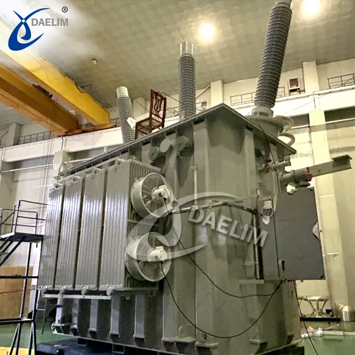
Power Transformer / Substation Transformer
Power Transformer and Substation Transformer usually has big dimension, to make sure that the nameplate can easily and clearly show the technical information of the transformer. Transformer manufacturer usually put the nameplate on one side of the transformer, with the height around 1600mm~1700mm, easy to see all the information in a prominent location.
Click here to know more about Power Transformer
Dry-type Transformer
 Dry-type Transformer can have a protection cabinet as an optional accessory. Therefore, the location of the nameplate will vary depending on the configuration.
For a dry-type transformer without a protection cabinet, the nameplate is placed on the side of the transformer’s main body, as the front and back are used for cable connections. The size of the nameplate depends on the transformer’s capacity, but it is usually smaller than that of a power transformer.
For a dry-type transformer with a protection cabinet, the nameplate is placed on the front of the protection cabinet. Because there is a large blank area on the protection cabinet, the nameplate can be made larger.
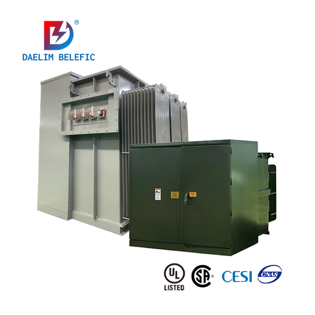
Pad mounted Transformer
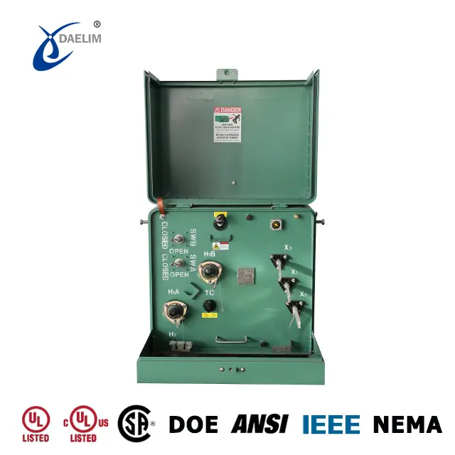
Based on the CSA C227.4-06 standard and ANSI/IEEE C57.12.34 standard, three phase pad mounted transformer nameplate shall be inside of transformer door, on the top of low voltage part.
Click here to learn more about Pad mounted Transformer
Transformer Nameplate Information
 Under the specified operating environment and operating conditions, transformer nameplates are typically marked with the main technical data. The following information should be provided: measured capacity, measured voltage and tap, measured frequency, wound connection group, and measured performance (impedance voltage, no load current, no load loss, and total weight).
A. Rated capacity (kVA): For example, the capacity specified on the transformer nameplate is the rated capacity, which means that the tap changer is located in the main tap, and is the product of the rated no-load voltage, rated current and the corresponding phase coefficient. For three-phase transformers, rated capacity = rated no-load line voltage x rated line current, and the rated capacity is generally expressed in kVA or MVA.
B. Rated voltage (kV): The maximum voltage a transformer can withstand for an extended period of time. To meet the changing needs of the grid, the high-voltage windings of the transformer are tapped, and the output voltage of the low-voltage winding is adjusted by adjusting the number of turns of the high-voltage winding.
C. Rated current (A): The current allowed to flow continuously through the transformer for a long period of time.
D. No-load loss (kW): The active power absorbed when one winding is connected to the terminals of the rated voltage while the remaining windings are open-circuited. There is a relationship between the performance and manufacturing process of the silicon steel sheet, as well as the applied voltage.
E. No-load current (%): When the secondary side of the transformer has no load at rated voltage, the current flowing through the primary winding is zero. Typically expressed as a percentage.
F.Load loss (kW): Short-circuit the secondary winding of the transformer and pass the rated current through the primary winding at the rated tap position, as this is the power consumed by the transformer at this time.
G. Impedance voltage (%): The primary winding of the transformer should be gradually increased in voltage by short-circuiting the secondary winding. The voltage on the primary side is equal to the short-circuit current of the secondary winding when the secondary short circuit current is equal to the rated current. The rated voltage is usually used. This is expressed in percentages.
G.The number of phases and frequency: The difference in temperature between the winding or oil surface of the transformer and its surrounding environment is the temperature rise. For oil-immersed transformers, the maximum temperature rise limit is 65°C, and the maximum temperature rise for oil surfaces is 55°C.
H. Temperature rise and cooling: The difference in temperature between the winding or oil surface of the transformer and its surrounding environment is the temperature rise. For oil-immersed transformers, the maximum temperature rise limit is 65°C, and the maximum temperature rise for oil surfaces is 55°C. Also, there are many methods of cooling: self-cooling by oil immersion, forced air cooling, water cooling, tube types, sheet types, etc.
Also, there are many methods of cooling: self-cooling by oil immersion, forced air cooling, water cooling, tube types, sheet types, etc.
Oil cooling transformer will be marked as ONAN, or KNAN (with vegetable oil). Transformers with cooling fans will be marked as ONAF or KNAF (with vegetable oil).
Dry-type Transformer's cooling system will be marked as AN or AF (with cooling fans).
J. Insulation level: There are insulation grade standards. Using the formula LI200AC85/LI75AC35, a 35kV transformer with a low voltage rating of 10kV can have a high voltage rating of 200kV and a power frequency rating of 200kV. The lightning impulse withstand voltage is 85 kV, the low voltage withstand voltage is 75 kV, and the power frequency withstand voltage is 35 kV. Although the withstand voltage is 35kV, it can be ignored due to the low voltage of 400V.
K.Connection group label: Transformer windings can be connected differently depending on the phase relationship between first and secondary windings. Such combinations of transformer windings are known as transformer winding connection groups. It is convenient to use the clock notation to distinguish between connection groups, that is, the long needle of the clock represents the high-voltage side lines voltage and the short needle represents the low-voltage side lines voltage. Numbers are used as labels for connection groups. Using Dyn11, for example, this is an indication that the primary windings are (delta) connections, and the secondary windings are (star) connections with a center point, and the group number is (11) points.
Reading more about Transformer Connection
How To Read A Transformer Nameplate?
Since the nameplate is so important that showing detailed technical informaiton on it, how can we read a transformer nameplate and what can we know by reading the transformer nameplate?
First, let’s take this reference drawing of three phase pad mounted transformer nameplate from Daelim Transformer.
In the first line, you can see the type of transformer “THREE PHASE LOOP PAD MOUNTED TYPE”; cooling system “ONAN”, which means the transformer are immersed by mineral oil, self cooling without cooling fans; frequency is 60Hz for North American market and temperature rise is 65℃.
On the left part of the pad mounted transformer nameplate, shows the rated capacity (kVA); impedance (5.75%); BIL of high voltage and low voltage, based on standard’s requirements; high voltage and low voltage (V) with connection (Delta / Wye / Grd); detailed informaiton of bay-o-net fuses and load break switch.
On the right side of the pad mounted transformer nameplate, we can see the weight of transformer body and oil, the number doesn’t show up on the drawing, and will be laser printed on the nameplate after the transformer finished the production. Engineer team will put the precise data on the nameplate. After that is the efficiency, data is based on the transformer standard requirements. The last two numbers will be the detailed information of current limiting fuse and load break bushing inserts (insulation class).
In the middle of pad-mounted transformer nameplate, is the tap changer taps information. In this case, customer asked for 5 taps tap changer, here it show the voltage % of these 5 taps, and the position of 5 taps (A, B, C, D, E).
After the taps information, there comes the electric diagram, connection diagram, and energy efficiency standard. A professional electric engineer can see how this transformer work from this part on the nameplate, the connection group information and efficiency standard are also showed up clearly so customer’s engineer can check if the data sheet from manufacturer are 100% meets the local standards.
In the bottom of the pad-mounted transformer nameplate, shows the P.O. number; Date manufactured; Standard of this transformer; MANUF.REF.NO.; and the manufacturer information, such as manufacturer name, website, phone number, email. So if there are any problem happened on the transformer, user can contact the manufacturer easily and fastly.
For Pad mounted Transformer nameplate, we can learn more from the CSA C227.4 standard, to know it more officially:
(a)Pad mount type ONAN 60Hz, 65℃;
(b)Number of phases: 3;
(c)Rating in kilovolt amperes;
(d)Identification number (e.g. serial number);
(e)Per cent Impedance at 85℃ (one decimal minimum);
(f)Oil volume in Iitres;
(g)BIL (basic Impulse Ievel);
(h)Total mass (Including Iiquid);
(i)Rated high and low voltage;
(j)<2 ppm PCB;
(k)Bayonet fuse and CLF fuse Identification;
(l)Tap voltages as a per cent of rated voltage and corresponding position of tap switch;
(m)Terminal markings, including physical identification, diagram of connections, and vector diagram;
(n)Year and month of manufacture;
(o)CSA Standard number;
(p)Manufacturer reference number;
(q)Name of manufacturer and address;
(r)Energy efficiency in accordance with CAN/CSA-C802.1; and
(s)If the option specified in clause 10(r) is selected by the purchaser, a warning in accordance with Clause 10(r).
Note: Where applicable, “ONAN”, as specified in item (a), may be replaced with “KNAN” or “LNAN”.
Other Labels And Markings On The Transformer
 Beside on the transformer nameplate, there are also other labels or markings on the transformer. Let’s take CSA standard three phase pad mounted transformer as an example.
Warning labels:
(a)“Keep away” warning sign. On the back side of low voltage door.
(b)Welded container label.
(c)Off-circuit switch label
(d)“Do not open” warning label. On the outside both doors.
(e)Non-PCB sticker. On the left side of transformer body.
Markings:
(a)Gross weight of transformer. On the side of transformer body.
(b)Information tag. In the upper left corner, includes serial number; purchaser’s stock code number; and manufacturer;s name or logo.
(c)Stock code number. Shall be stencilled on the front of the cabinet.
After receiving the advance payment from customer, Daelim engineer team will prepare the production drawing, indlucing the nameplate drawing. DaelimTransformer team will send the drawings to our customer for a detailed review. If the customer has any questions, we can clarify before start the production. If there are no questions, our customer will need to sign on the production drawing and the nameplate drawing. So Daelim factory will start to produce based on the signed drawing that was confirmed by the customer.
For Latin America market and Canada market, Daelim can also prepare the transformer nameplate in Spanish or French as customer’s requirements.
If client wants to do OEM business with Daelim, we can open to discuss, and can put client’s brand name with other information on the transformer nameplate.
After reading today’s article, you should know how to read a transformer nameplate, and how to know more technical details through the transformer nameplate. If still have some questions, or if there are any project needs, welcome to contact Daelim Transformer, with over 20 years of international electric market experience, we will support you with a suitable technical solution, a competitive price offer, and a safe & fast shipping solution.
Related Products
Related Article
Causes and Measures for Abnormal Transformer Temperature
Abnormal transformer temperature can result from internal faults, unopened radiator doors, blocked or leaking respirators, poor transformer structure, and cooling device malfunctions. Measures include identifying faults, opening doors, clearing respirators, installing magnetic isolation, and ensuring cooling device functionality.
Requirements for Transformer Core Grounding Points
Transformer cores must have a single grounding point to prevent floating potentials, short-circuit currents, and overheating. Improper grounding can cause insulation damage, increased iron loss, gas generation, and power interruptions, compromising transformer and grid safety.
Manifestation Characteristics of Transformer Core Grounding Fault
Transformer core grounding faults cause overheating, gas production, and insulation damage. Symptoms include increased hydrocarbons in oil analysis, high grounding current, and visible core burns or discharge marks. Accurate diagnosis requires comprehensive testing, electrical measurements, and visual inspections.
Prevention and Treatment Measures for Transformer Core Grounding Faults
Prevent transformer core grounding faults by ensuring proper insulation, regular current measurements, and chromatographic analysis. Address faults with temporary measures, inspections, and targeted repairs. Emphasize design and manufacturing standards to prevent faults and ensure safe operation.
The Harm of Outlet Short-Circuit Faults to Power Transformers
Outlet short-circuit faults in power transformers cause winding deformation, insulation damage, and overheating, affecting dynamic and thermal stability. Analysis via oil chromatography and electrical testing guides timely repair planning.
Measures to Prevent Transformer Short-Circuit Accidents
Enhance transformer resilience against short circuits by optimizing design, strengthening insulation, improving maintenance, and upgrading protection systems to ensure reliable grid operation and minimize downtime.

