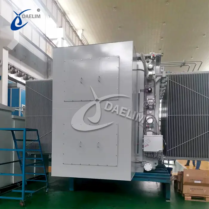
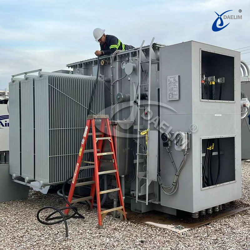
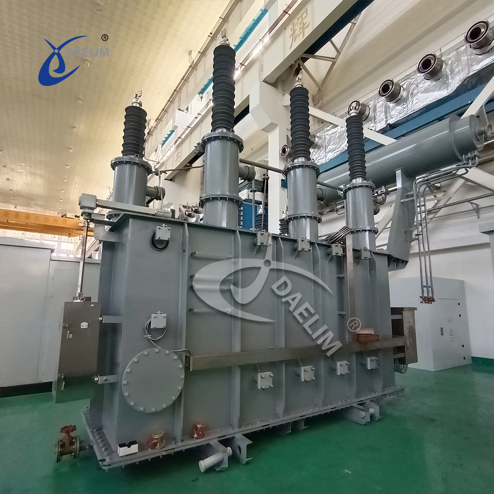
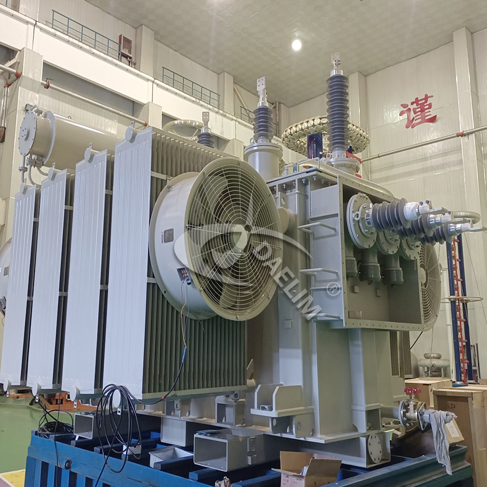
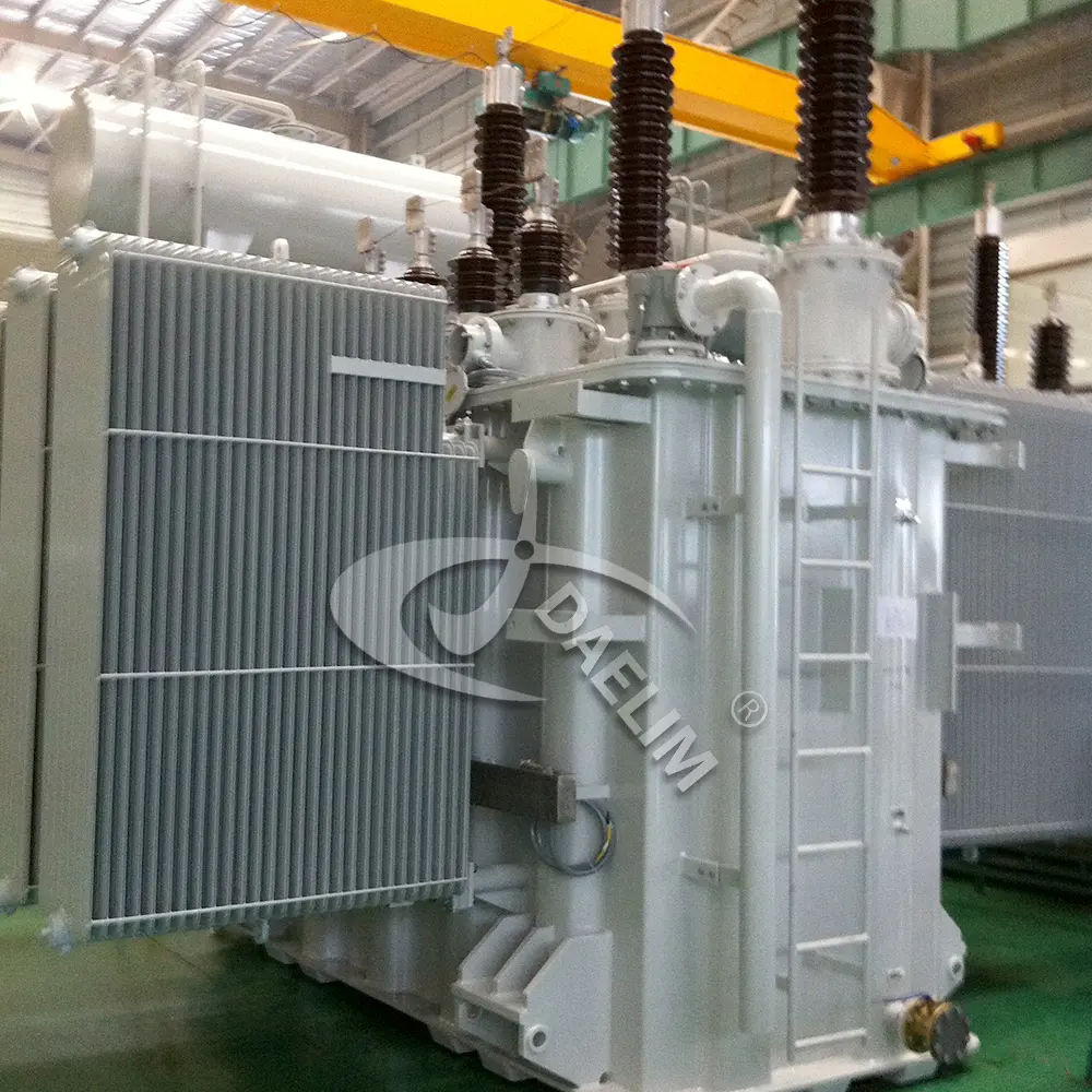
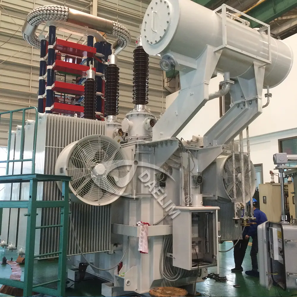
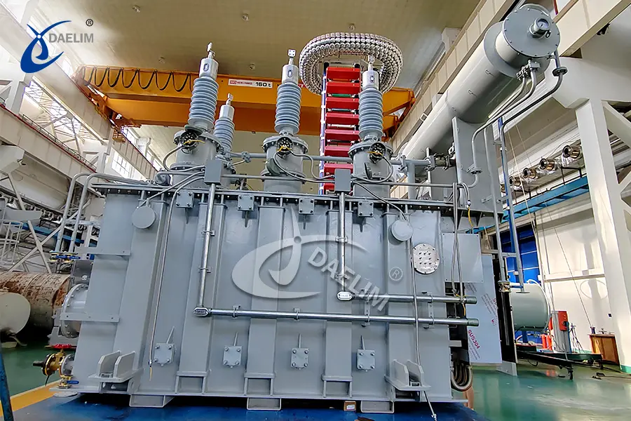
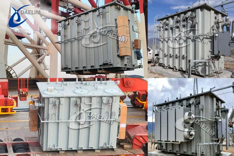
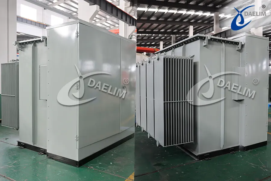
220kV 63 MVA Power Transformer


- Primary Voltage Ratings: 220kV
- Secondary Voltage Ratings: 30/11kV
- H.V. TAP RANGE: 220kV ±1.25%×10 tapping positions
- CONNECTION TYPE: YNyno d11
- TYPE: 3 PH 3 winding conservator type
- Standards: IEC
- Power Rating: 47.5MVA, 63 MVA
- Cooling Method: ONAN/ONAF
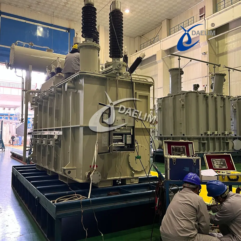
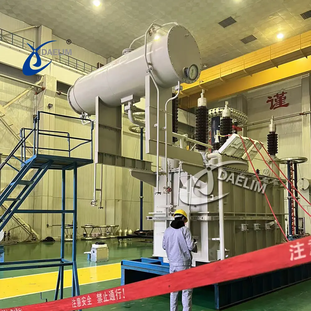
The 220kV, 63 MVA power transformer is an outdoor conservator type with an on-load tap changer (OLTC) and an ONAF cooling system. It operates in Libya's extreme temperatures, with a core and windings designed for high efficiency and durability. The transformer features a robust tank with protective coatings, a conservator with an oil-seal breather, and various valves for maintenance. Protection includes Buchholz relays, temperature indicators, and pressure relief devices. The OLTC offers 21 tapping positions for precise voltage control.
Quote Now
Overview:
The 220kV, 63 MVA power transformer is an outdoor, conservator-type unit equipped with an on-load tap changer (OLTC). The cooling system utilizes natural oil circulation and forced air (ONAF), and includes a winding temperature relay, an auto-manual switch, and a control box housing control devices.
Service Conditions:
The transformer is designed for continuous operation under the following site conditions in Libya:
-
Maximum altitude: 1,000 meters above sea level
-
Maximum ambient air temperature: +50°C
-
Minimum ambient air temperature: -5°C
-
Monthly average temperature of the hottest month: 40°C
-
Yearly average temperature: 30°C
Rated Power
| Rated voltage ratio (kV) | Rated power |
Tap changing | |
| ONAN | ONAF | ||
| 220/30/11 | 47.5MVA | 63MVA | OLTC |
Highest voltage for equipment and rated frequency
|
| H.V winding | L.V winding | Tertiary winding |
| Nominal voltage (kV) | 220 | 30 | 11 |
| Highest voltage for equipment (kV) | 245 | 36 | 12 |
| Rated frequency (Hz) | 50 | 50 | 50 |
63 MVA Transformer Vector group and winding connection
| Rated voltage ratio (kV/kV) | 220/30/11 |
| Vector group | YNyno d11 |
| Connection of HV windings | Y (3-phase 4-wire) (Neutral point solidly earthed) |
|
Connection of LV windings | Y (3-phase 4-wire) (Neutral point earthed through resistor) |
Core:
The core is constructed from high-grade cold-rolled grain-oriented steel sheets, securely clamped to reduce vibration and minimize noise. The core assembly includes insulating material on both sides of individual stampings, resistant to oil and temperature. The complete core is effectively earthed.
Windings:
The HV, LV, and tertiary windings are made from high-conductivity, drawn copper coils. All turns are adequately supported to prevent movement. The windings meet mechanical, thermal, and electrical requirements and are fully insulated according to IEC 60076 standards for a system's highest voltage of 245kV, 36kV, and 12kV. They are wound with strong bracing and securing tapes to form a self-supporting structure, with adequate cooling ducts to ensure temperature rise remains within permissible limits under normal operating conditions. Insulation material used for the windings and connections is Class A. The tertiary winding is for stabilization purposes only and is not intended to carry any load.
Radiators:
The radiators are hot-dip galvanized and painted to prevent oil leakage and ensure vibration-free operation regardless of wind velocity and atmospheric conditions. They feature sturdy construction and are strongly fastened to the tank.
Tank Finish:
- External: The tank, cover, and oil conservator are sandblasted or shot-blasted before being coated with a two-pack epoxy primer. The final finish is a two-pack polyurethane paint with a total thickness of over 180 µm.
- Internal: The interior of the transformer tank is coated with a two-pack epoxy primer to a thickness of approximately 30 µm.
- Radiators: The external surfaces of the radiators are hot-dip galvanized with a thickness of over 60 µm.
Conservator:
- Design: The transformer features an overhead conservator tank, connected to the main tank and tap changer tank at the highest point to prevent air or gas entrapment under the main tank cover.
- Capacity: The conservator tank has adequate capacity for oil expansion and contraction under specified operating conditions.
- Features: Includes a bolted end plate for internal cleaning, filling cap, drain valve with captive cap, oil level indicator, and valves to isolate the oil supply to the transformer and tap changer tanks. It is equipped with an oil seal type silica gel breather, and internal surfaces are treated with oil-resistant coating. A membrane (air bag) separates the oil and air to prevent moisture contamination. The conservator is designed to withstand internal pressure of 35 kPa and full vacuum without leakage or distortion, and is equipped with lifting eyes for removal.
Oil Level Indicator:
The oil level indicator on the conservator tank displays oil levels at all temperatures, with minimum, maximum, and normal level markings clearly visible from normal access levels.
Valves:
The transformer is equipped with the following valves:
- Oil filtering valves at the bottom and top of the main tank
- Drain and filling valve for the conservator tank
- Drain valve for the main tank
- Drain valve for the OLTC tank
- Valves between the main tank and conservator tank, and between the OLTC tank and conservator tank
- Valves between the main tank and each radiator
- Drain valves for each radiator
- Oil sampling cocks for the main tank and OLTC tank
- Other necessary valves
Protection Devices:
The transformer includes the following protection devices:
- Buchholz relay with alarm and trip contacts
- Oil temperature indicator with alarm and trip contacts
- Winding temperature indicator with maximum pointer and alarm/trip contacts
- Pressure relief device with trip contact
- Buchholz relay for the OLTC with trip contact
Buchholz Relay:
- Fitted to the oil feed pipes from the conservator tank to the transformer tank and tap changer tank.
- Mounted to ensure all gas from the tanks passes into the Buchholz relay.
- Alarm contacts close upon gas collection, and trip contacts close in response to oil surge or low oil levels. The relay includes a gas collection facility and a gas releasing valve with a suitable operating position.
Oil Temperature Indicator:
- Indicates the hottest oil temperature.
- Features a dial-type indicator with a pointer to register the highest temperature reached, which can be reset.
Winding Temperature Indicator:
- Indicates the maximum winding temperature.
- Features a dial-type indicator with a pointer to register the highest temperature reached, which can be reset.
Pressure Relief Device:
- A suitably sized device mounted on the tank cover for rapid pressure release.
- Maintains oil tightness under all normal service conditions and prevents moisture ingress or oil leakage after operation.
On-Load Tap Changer (OLTC):
- The HV winding includes a vacuum-type OLTC with 21 tapping positions, including principal tapping and ±1.25% × 10 tapping positions, operated by an on-circuit tap switch.
- The OLTC is designed to handle the rated current and 20% overload current of the transformer. All phases are adjusted to the same tap position with a single operation.
Related Products


Quote Now
Please Write your message, ask for price, we will reply you soon, thanks

