Guide to Transformer Harmonics and K-Factor
Flickering lights, breakers tripping off, and overheating transformers? That's probably the transformer harmonics lurking within your power system.
These are only some of the few manifestations that harmonics are present in your power system. So, how do you address them? That's where the K-factor gets into the picture.
In this article, we will tackle transformer harmonics, what it is, what are its effects, what are the possible solutions, and how k-factor can help you handle them.
Contact Daelim Transformer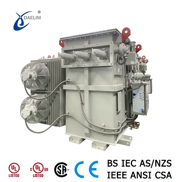
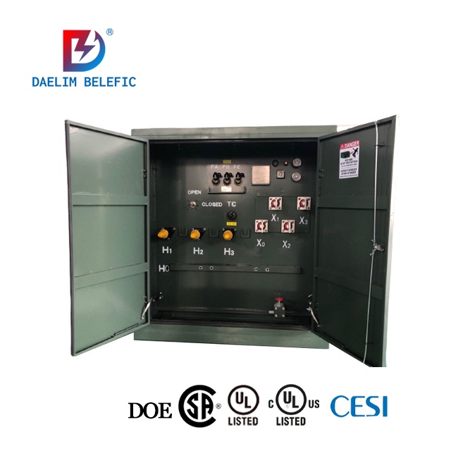
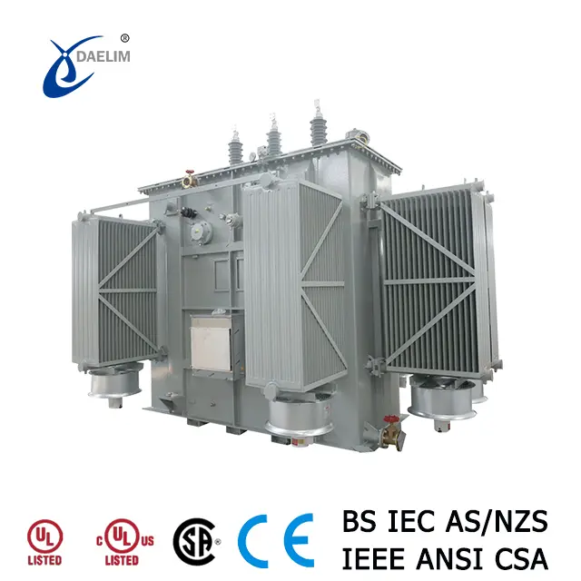
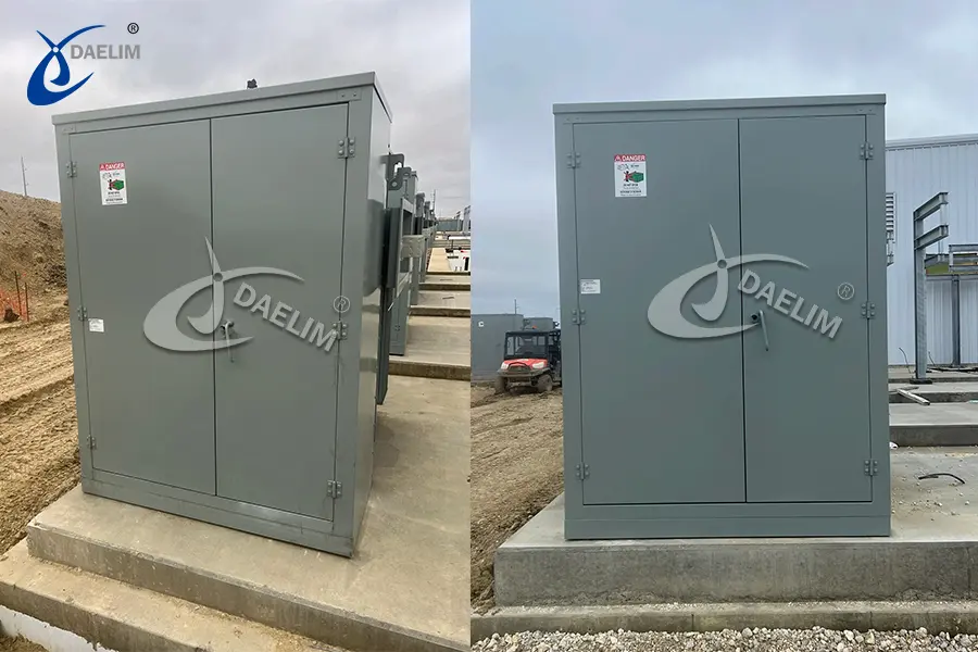
High voltage up to 46kV and power rating up to 20MVA with UL Listed
Harmonic loading or specified K-factor
Side-mounted or top-mounted bushings
HV &LV air terminal compartments
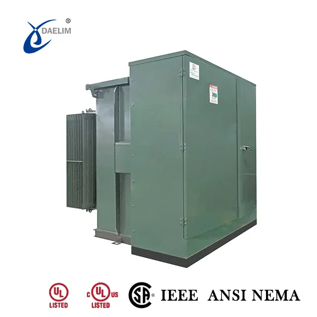
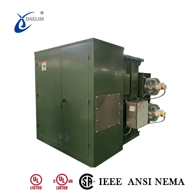
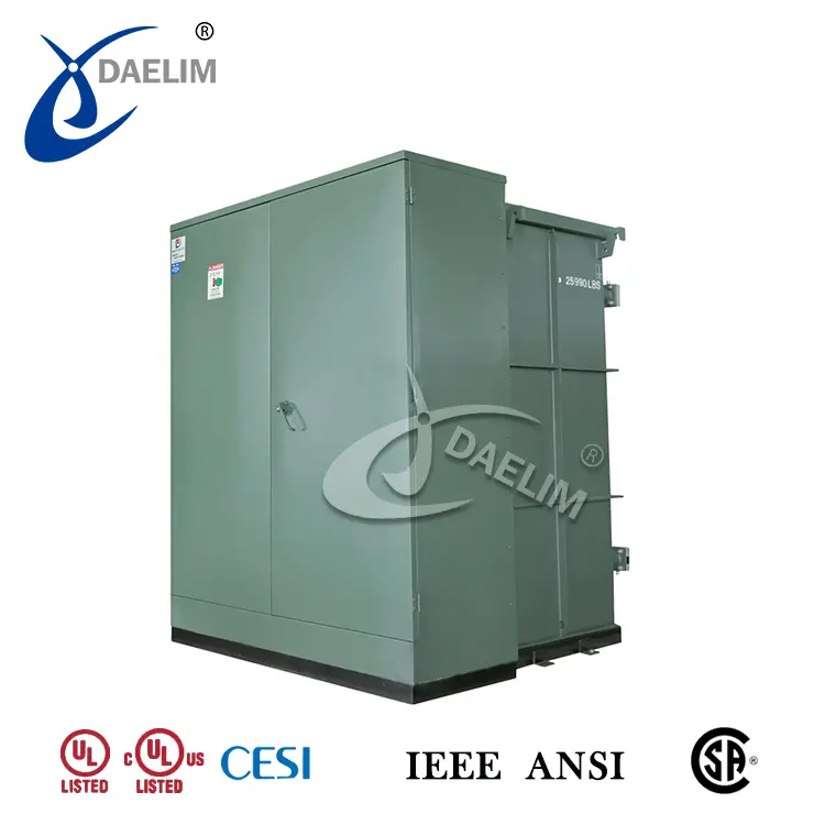
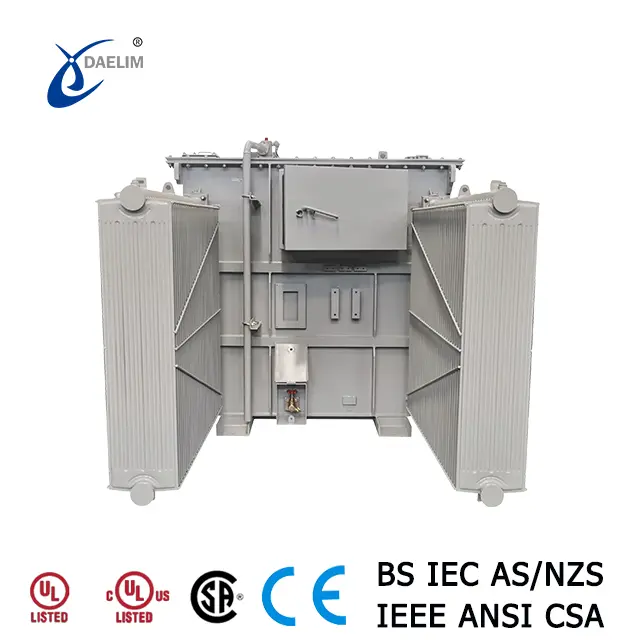
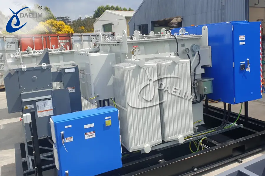
High voltage up to 44kV and power rating up to 10MVA with UL Listed
Harmonic loading or specified K-factor
ANSI, IEEE, DOE, CSA, NEMA
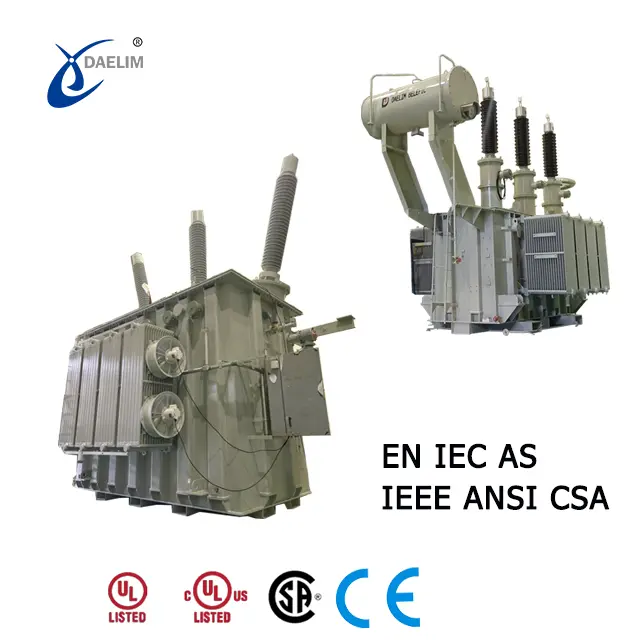
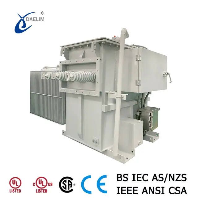
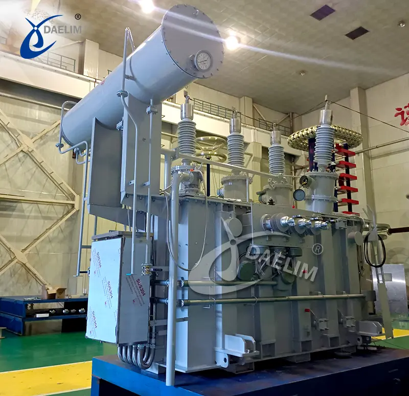
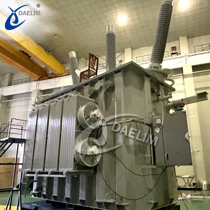
High voltage up to 345kV and power rating up to 500MVA
Harmonic loading or specified K-factor
ANSI, IEEE, CSA, AS, IEC, EN Standards
What Does Harmonics Mean in the Power System?
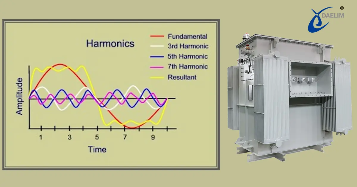
Harmonics in the power system could be quite complex. However, when you look closely, harmonics are simply the waveform deviations observed in the current or the voltage with respect to the fundamental frequency.
In short, distortion. These distortions are characterized to have higher frequencies than 50z/60hz which can reach 2nd, 3rd, 4th, 5th order, or higher.
How Are These Harmonic Orders Translated?
The order number serves as the multiplier. To get the harmonic frequency, multiply the order number by the fundamental frequency.
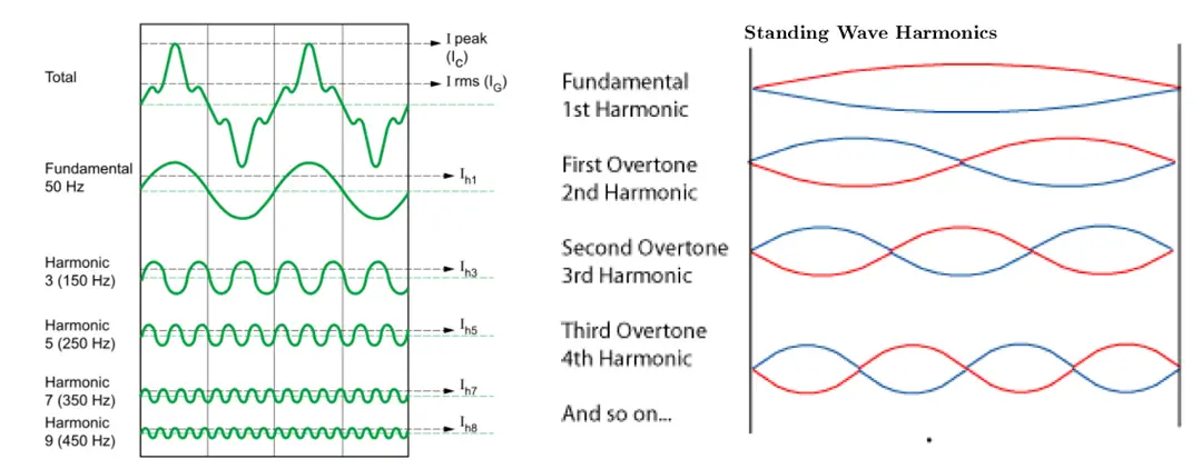
For example, if your transformer is designed to run at 60Hz, the 2nd harmonic doubles the value of the base frequency and should surface at 120Hz. Likewise, the 3rd harmonics triple at 180Hz, the 4th harmonics quadruple at 240Hz, and so on.
You may enjoy: MV Skid Compact, Premier Choice for Utility-Scale Solar and Energy Storage
Where Do Harmonics Come From?
Harmonics comes from certain types of loads which can either be non-linear loads or other loads that can cause over-excitation.
These loads can come from modern devices like EV chargers, computers, TVs, printers, and lighting. Harmonics can also come from large equipment like pumps, chillers, rotating machines, and electric arc furnaces.
Typically, these are loads with variable impedance and draw current in an erratic manner. This creates current distortions which then result in voltage distortion.
How Does Harmonics Affect a Power System?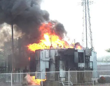
Generally, harmonics are considered an impurity in the power system and just like any other impurities they can have several negative effects on the power quality and severely damage critical equipment like the transformers.
Power Quality Issues
Harmonics can result in poor power output and increased power consumption which results in higher electricity costs.
The distortions in the voltage or current may also send wrong signals to fuses and capacitors causing them to trip off more often than necessary resulting in downtimes and a decrease in overall productivity.
The sudden spike in the current or voltage can likewise cause overloading since the load may go beyond what the system is designed for.
Effects on Transformers
Harmonic from non-linear loads and over-excitation makes the transformer work more than what is required or its rated capacity.
When this happens, the temperature of the transformer can drastically rise and eventually overheat. This is where most problems arise.
Excessive heat may damage the parts of the transformer, particularly its insulation. Through time, it slowly degrades the cooling system which can lead to breakdowns and shortened lifespan.
Not only that, but it also affects the vital parts of the transformer, the core, and its windings which leads to increased iron and copper losses.
How To Handle the Presence of Harmonics in the Power System?
Harmonics can be quite devastating but the good news is, they are highly manageable. Depending on the type of application or power system set-up that you have, with good engineering, harmonics are almost, if not always, predictable.
For example, an IT hub or facility that maintains inverters, LED lighting, and tons of switch-mode power supplies like computers should include mitigating measures to counter current harmonics as these units fall under non-linear loads and suck current in a frenzy manner.
More resource: How To Manage Transformer Inrush Current?
There are several options to effectively manage the effects of harmonics in the power system such as using harmonic filters, transformer derating, and K-rated transformers.
However, choosing a transformer designed to handle harmonic generating loads is one of the safest options.
More resource: Guide to EV(electric vehicle) Charging Station Transformers
What Do You Mean by Transformer Derating?
Derating is when a transformer is loaded at a rate lower than its rated capacity. Similar to oversizing a transformer, this is done to protect the transformer from potential damages caused by the load and other environmental conditions.
Derating is not only used to anticipate the effects of harmonic loads but this option is also considered when installing transformers at higher altitudes and whenever unconventional mounting is needed.
When opting to derate a transformer, computing the derating factor should be considered. This can also be derived by using the values of the system’s K-factor or THD(Total Harmonic Distortion).
Moreover, derating a transformer does not ensure long-term protection from harmonics, and K-rated transformers are still a more viable solution.
What Makes K-Rated Transformers Different From Standard Transformers?
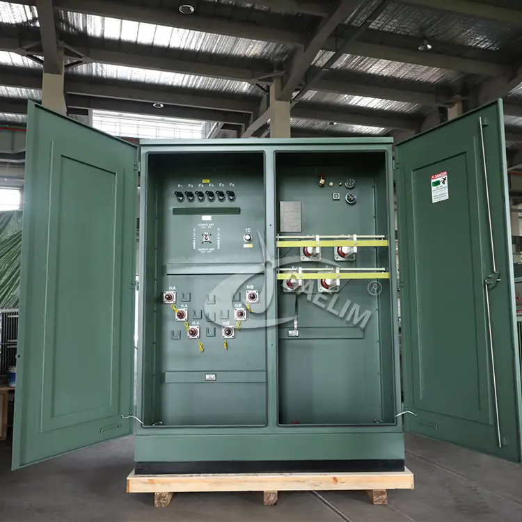
K-rated transformers are built with more robust insulation, ample air ducts, and pumped-up neutral conductors.
The core and the windings are made with higher specifications and top-grade material that helps them endure the additional heat and stress caused by the load accompanied by rich harmonics.
Electrostatic shielding in between windings is also used to further protect the winding materials from the heat from increased eddy currents.
To accommodate all these improvements in the design and construction, K-factor rated transformers are significantly larger and more pricey than standard transformers.
How To Find the Most Suitable K-Rated Transformer?
The K-factor rating determines the thermal capacity of the transformer in terms of the harmonics produced by the load.
This will tell how well the transformer can maintain optimum performance and withstand high levels of harmonics without overheating or breaking down.
It is represented by a numerical value from 1 to 50, where K-factor 1-rated transformers are standard transformers whose thermal capacity can only cater to linear loads.
While K-factor 50-rated transformers have the highest thermal capacity which can handle a tremendous amount of excess heat from higher order harmonics. This type is costly and used only in an overly demanding environment.
Reading more: Why do PV systems use double-split step-up transformers?
To find the most suitable K-factor rating the percentage of the devices or load which produces harmonics should be determined or the Total Harmonic Distortion should be accounted for.
K-1 Rated Transformer
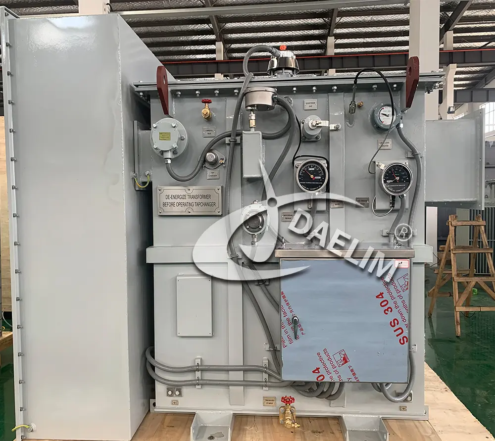 Although it is represented with a K-1 rating these types of transformers mean a transformer that is not K-rated.
 - It can only sustain average temperature rise from eddy current and is not capable of handling non-linear loads.
- Mostly used for linear loads like standard incandescent lighting, capacitors, heaters, and motors. In case non-linear devices are present, it should not be more than 15% of the load.
K-4 Rated Transformer
- This is suitable for power systems with relatively low to medium levels of harmonics. It can handle systems with harmonic generating devices of about 35% or below.
- Its ability to withstand heat increase from harmonics is 4 folds greater than a standard or non K-rated transformer.
- Sample application includes fluorescent lighting, AC drive, PLCs, Silicon Controlled Rectifiers, and induction heaters.
K-13 Rated Transformer
- The most commonly used transformer for power systems with medium to high harmonic levels. It can handle up to 75% harmonic generating devices.
- In terms of heat resistance, this transformer can handle 2 times the capacity of a K-4 rated transformer.
- Its main applications include manufacturing lines, telecoms, Uninterrupted Power Supply, educational facilities, and medical facilities.
K-20 Rated Transformer and Higher
- This type has superior non-linear load thermal capacity. It has the ability to sustain up to 100% of the load made up of harmonic generating devices.
- Transformers with this K-factor rating and higher are typically for specialized applications such as data processing facilities, administrative buildings, solar farms, variable speed drives, and other commercial and industrial applications.
What Are the Benefits of Using a K-Rated Transformer?
The main benefit of using K-rated transformers over standard transformers is that they are made with higher tolerance to harmonics.
This lowers the chances of overheating which leads to added benefits such as fewer downtimes due to maintenance and power interruption.
Learn more: Guide to Transformer Maintenance
K-rated transformers are also more sturdy and reliable. All of these features help improve the efficiency of the system.
What Are the Downsides of Using a K-Rated Transformer?
The major downside of K-rated transformers is that they are not cheap. The price generally goes higher with higher K ratings.
Also, note that K-rated transformers do not eliminate harmonics in the power system but only serve as a countermeasure.
How To Calculate the K-Factor?
There are different ways to calculate the K-factor. This could defer depending on the standards and other basis. Below is the K-factor formula according to the UL1561 standards.

Where,
h = harmonic order
Ih (pu) = RMS current as per harmonic current per unit RMS load
The K-factor value serves as the basis for manufacturing K-rated transformers. The value of the K-factor is directly proportional to the amount of heat produced due to harmonics.
How To Calculate the Total Harmonic Distortion?
Total Harmonic Distortion or THD calculations can be automated with the help of an instrument called a THD spectrum analyzer or a power quality analyzer. Moreover, it can also be calculated theoretically using the formula below.

Where,
I1 = Fundamental
I2 = 2nd order harmonic current
I3 = 3rd order harmonic current
I4 = 4th order harmonic current
I5 = 5th order harmonic current
Calculating and monitoring the THD is one way to get an actual overview of the distortions within a system. These are sets of vital information needed in studying and resolving issues related to harmonics.
The Daelim Transformer Approach to Harmonics
Rapid modernization brought about undeniable growth in the area of tech and electronic industry. The increasing demand for computers and other electronic devices highlights the importance of embracing harmonics instead of considering them as an adversity.
As a transformer manufacturer, it is high time for us to view harmonics as a necessary factor that we all need to adapt to.
Daelim Transformer is a highly competent transformer manufacturer that can produce tailor-made transformer designs that aim to target power system pain points such as harmonics.
Here at Daelim Transformer, we combat harmonics head-on with our extensive transformer customization which includes K-factor considerations and other modifications.
Apart from that, Daelim also takes pride in delivering various solutions for effective power management and distribution. Serving diverse high tech sectors such as data centers, solar farms, and crypto mining industries.
If you are in search of a transformer manufacturer that could help you with harmonics, Contact us now. Come explore different transformer options and discover wonderful possibilities with Daelim Transformer
Related Products
Related Article
13.8 kV 10.5 MVA Substation Transformer for Ecuador
A customer from Ecuador contacted Daelim Transformer for a 10.5MVA substation transformer (13.8kV high voltage, 2.4kV low voltage). Daelim Transformer provided a customized solution, conducted virtual factory tours, ensured rigorous quality control via video inspections, and offered post-delivery online training and ongoing support, fostering a successful partnership.
2600 kVA Pad Mounted Transformer for Cryptocurrency Mining
Daelim Transformer successfully provided three customized 2600 kVA pad mounted transformers to power a state-of-the-art cryptocurrency mining facility in Texas, USA. Our transformers were meticulously designed to meet the unique demands of the mining operation, ensuring seamless power distribution with unwavering reliability and efficiency.
20MVA Power Transformer for the United States
This project involves the development of a 20 MVA three-phase power transformer tailored for the United States market. The primary voltage is 24.94kV, and the secondary voltage is 4.16kV, indicating it functions as a step-down transformer. The design and production fully comply with IEEE C57.12.00 standards and have passed third-party UL team testing. All accessories also adhere to IEEE standards. FR3 vegetable oil serves as the insulating liquid for the transformers.
1500 kVA Transformer for Australian Mining Project
Introduce the 1500 kVA transformer tailored for Australian mining projects. The transformer operates in a three-phase configuration, with a total of four units deployed. Notably, its primary voltage stands at 11kV, while the secondary voltage is 1kV. Characterized by its compact size, emphasis on safety, and unwavering reliability, this transformer is meticulously designed and manufactured to meet the stringent requirements outlined in AS 60076 and AS efficiency value standards.Let's delve into the key features and specifications of this essential solution.
2 MVA Pad Mounted Transformer for Utility
Behold the backbone of Canada's utility infrastructure—the 2MVA pad mounted transformer. With a primary voltage of 4160Grdy/2400V and a secondary voltage of 800GrdY/461V, this transformer stands as a testament to efficiency and reliability in power distribution. Crafted in strict accordance with CSA standards and CAN/CSA802.1 energy efficiency guidelines, it embodies the pinnacle of engineering excellence.
2600 kVA Pad Mounted Transformer For Crypto Mine In Kansas
This morning, I received the on-site photos of the pad-mounted transformers from the customer, and I was overwhelmed with excitement and joy. These pad-mounted transformers are installed at a 20MW crypto mining site in Kansas, USA. A total of 5 sets of 2600 kVA pad-mounted transformers, all UL-listed, are being deployed at this site. Currently, 3 sets have already been installed onsite and are scheduled to be powered on imminently.

