How To Check Transformer Primary And Secondary?
Electric transformers regulate electricity for your homes and industries. They either step it up or step it down to the level that it is safe for use. Transformers regulate electricity through their winding and transformer windings are nothing more than an electrically conductor wire, usually copper wire, winding around a metallic object called core.
Electrical transformers are also an integral part of almost all electrical devices and failure of transformer means failure of electrical device. So, the question of how to check transformer primary and secondary is an important question for any electrician.
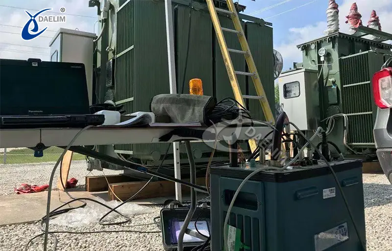
Contact Daelim TransformerTools and Equipment Needed To Check Transformer Winding
Transformer windings are a very simply designed part of the transformer and they do not need much to check and inspect. You only need a
- Multimeter to check the voltage and current values across the winding.
- Insulation resistance tester to measure the insulation resistance between winding layers.
- Safety gear like electrically insulated gloves, and clear hard plastic goggles to protect yourself while working.
Safety Precautions Before Checking Winding
Your safety is the first and most important thing followed by the safety of the equipment and surrounding area. So only do the process after you have complete knowledge on how to check transformer primary and secondary winding and have all the necessary tools. Ensure following things before starting checking the transformer winding.
First, initially disconnect the transformer from its power source. This will eliminate the risk of any accidental electrical shocks or equipment damage during the checking process.
Second, do a zero voltage check using a multimeter. Use a standard multimeter and check every input and output terminal of the transformer. There should be zero voltage reading on each of the terminals.
Third, make sure of the proper grounding. Whether you remove the winding or keep it inside the transformer for check, make sure that the winding or the transformer has been properly grounded. Grounding redirects stray currents away from personnel, reducing the risk of accidents.
Fourth, never touch transformer parts without proper knowledge. Avoid all types of unnecessary touch of all transformer parts, specially live parts. With even power off, some parts can retain a residual charge or have capacitive effects. Always treat electrical equipment with caution and use insulated tools for added safety.
How To Identify Primary And Secondary Of Transformer
 The primary and secondary winding of the transformer can be identified in a number of ways. Most easy and authentic way of checking this is to check the name plate attached to the winding. Most manufacturers have attached a name plate of primary or input on the primary winding and secondary or output to the secondary winding of the transformer.
If your transformer winding is still connected to the transformer, then observe which winding is connected with the power source, that one will be primary winding and other will be secondary winding.
If you have a winding from step down transformer which is most of the case in domestic appliances and installations. Then primary winding will be bulkier than the secondary winding. If you check the resistance with a multimeter, primary winding resistance will be higher than the secondary winding as primary has more wire turns than secondary.
How To Check Transformer Primary And Secondary With Multimeter
Checking the transformer primary and secondary using a multimeter is very easy and requires the following steps. First make sure you have taken all safety steps mentioned above.
- First step is to set up the multimeter to the resistance or continuity mode. Depending on the type of your multimeter, you either need to rotate the selection switch or place the red terminal in the resistance slot.
- Make sure the transformer winding is not connected to any power source.
- Place the terminals of the multimeter on the terminals of the winding. It does not matter which terminal is connected to which terminal of the winding. Just one terminal of the multimeter, one terminal of the winding and another with another terminal.
- If you have selected the continuity mode, then if you hear a beep from the multimeter, then it's an indication that the winding circuit is closed.
- If you have selected resistance mode, then observe the resistance reading you see on the multimeter.
- A functioning primary or secondary winding will show a moderate resistance value, depending on its design
- If the multimeter screen shows an infinite resistance value on the screen, then the winding has a broken wire, open circuit and needs repair.
- If a multimeter screen shows very low resistance that is resistance near to zero, then winding has a short circuit in it.
Advanced Techniques for Transformer Testing
Insulation Resistance Test
 Insulation resistance test is done to check insulation between windings and between winding and core. This is a crucial test that ensures whether windings are good enough to work or need repair. To perform an Insulation resistance test follow the below mentioned steps.
- First make sure that the transformer is not connected to the power source.
- Make sure that all terminals of the winding are clean from any type of dust, oil or grease.
- Make sure that the insulation tester is working properly and has its terminal cleaned.
- To check the insulation between any of the winding and core.
- Take an insulation tester aka megohmmeter and connect its one terminal with the terminal of the winding you need to check.
- Connect the other terminal of the meter with either the core or the ground.
- To perform inter-winding insulation testing, connect the probes between different winding terminals (e.g., primary to secondary).
- Now set the voltage of the meter according to the transformer specification.
- Start the test by applying the specific voltage for a fixed duration that is for one minute.
- Megohmmeter will show the reading of resistance between the selection two connections.
- Value of this resistance will be Mega Ohm and should lie above the manufacturer's minimum acceptable insulation resistance standards.
- A resistance value in the range of hundreds of megohms indicates healthy insulation with minimal current leakage. This suggests the insulation is dry, intact, and capable of withstanding the applied voltage.
- A low resistance value (e.g., below 1 MΩ) indicates potential issues, such as moisture ingress or contamination.
More resource: How to test a power transformer?
Testing for Winding Polarity
Transformer winding polarity testing is important to check the phase relationship between primary and secondary winding. Winding can either be in phase or out of phase with each other and only in phase relationship between the winding is required.
Follow the following steps to check the transformer winding polarity.
- First make sure the transformer and its winding is disconnected from all power sources.
- Label terminals of the winding, label P1 and P2 to the two terminals of the winding and S1 and S2 to the two terminals of the secondary winding.
- Set the multimeter to measure voltage.
- Now apply a low AC voltage to the two terminals of the primary winding.
- Now use a multimeter to measure voltage at both primary winding and at secondary winding. To measure the voltage, attach a voltmeter in parallel to the winding terminal. Never attach it in series for measuring voltage.
- Note down the primary and secondary winding voltage.
- You also need to measure the combined voltage of the transformer winding. To measure that, attach a red terminal to the incoming terminal on primary winding, let say P1 and black terminal to the outgoing terminal of secondary winding let say S2.
- Note down the combined winding voltage.
- If the combined voltage of the winding is equal to the sum of the primary and secondary voltage, then your transformer windings are in phase.
- If the combined voltage of the winding is equal to the difference of the primary and secondary voltage, then your transformer windings are out of phase.
Importance of Checking Transformer Windings
 As transformers work as the backbone of our electrical systems and their failure has to be prevented at every cost. Checking transformer winding offer following benefits
- Continuous checking of transformer winding helps detect and remove issues at early stages thus ensuring reliability in performance and operations.
- Addressing all issues at early stages prevent catastrophic failure of transformer or transformer explosion that can be dangerous for surrounding and connected equipment.
- Continuous checking of transformer winding increases safety and reduces risk of hazards like electrical shock, fire, and short circuit between windings.
- Regular monitoring and maintenance of transformer windings prolong their service life, protecting your investment and avoiding the need for frequent replacements.
Conclusion
Transformers are vital components of electrical systems. Their regular winding checks ensure their reliability, safety, and longevity. Using tools like a multimeter and insulation tester, one can diagnose issues like open circuits, short circuits, or insulation breakdowns. Proper maintenance prevents catastrophic failures, enhances operational safety, and extends the transformer's service life.
Follow Up
Windings are the transformer's most crucial part and need continuous inspection and maintenance. Dealim’s offer best quality transformer windings of all types, sizes and capacity by following standards like ANSI, IEEE, CSA, AS, GOST, IEC, EU, and DIN/VDE.
We have fully functional distribution and facility centers and a strong customer base in the USA, Europe, Canada, Australia, and all others around the globe. If you have any query about transformers, just Contact Us and we will talk you through the process.
Related Products
Related Article
Key Principles of High Voltage Transformer Design
High voltage transformers are crucial for efficient power transmission, stepping up or down voltages above 35 kV and 10 MVA. Their design involves advanced materials, including high-grade silicon steel and amorphous metals, along with specialized insulation and cooling systems. Key challenges include managing high voltage stress, heat, and electromagnetic forces. Future trends focus on smart technology integration, sustainability, and advanced materials for enhanced efficiency.
Aluminum vs Copper Transformers
Copper transformers are more efficient, durable, and better at heat dissipation, making them ideal for high-load and long-term industrial applications. Aluminum transformers, while more cost-effective and lightweight, are less efficient, prone to wear, and better suited for low to moderate loads in residential or small-scale uses. Hybrid systems combine both materials for optimized performance and cost-efficiency.
How to Ensure Safe Transformer Storage
Proper transformer storage is crucial for long-term reliability. Key steps include choosing a stable, weather-protected location, sealing openings, maintaining nitrogen pressure for liquid-filled transformers, and ensuring dry conditions for dry-type transformers. Regular inspections, moisture monitoring, and pre-service testing ensure optimal performance. Proper care prevents damage, extending transformer lifespan and reducing maintenance costs.
Transformer Shortage: Factors and Challenges of Current World Order
The global shortage of electrical transformers is driven by increased demand due to lifestyle shifts, population growth, and industrial expansion, particularly in electric vehicles, cryptocurrency mining, and AI data centers. National policies, supply chain disruptions, raw material shortages, and manufacturing constraints further exacerbate the issue. Daelim offers industry-focused solutions, leveraging multiple production facilities to meet demand and provide high-quality transformers in record time.
VPI Transformer vs Cast Resin
VPI and Cast Resin transformers are both dry-type transformers with distinct characteristics. VPI transformers use vacuum pressure to impregnate resin for enhanced insulation and moisture resistance, making them ideal for moderate environments and industrial applications. Cast Resin transformers, with solid epoxy resin construction, offer superior durability and fire resistance, suited for harsh environments like marine and mining. VPI transformers are cost-effective, while Cast Resin models have higher upfront costs but longer-term reliability.
How Long Does It Take To Replace A Transformer
Replacing a transformer involves several steps, including inspection, equipment transportation, removal of the old transformer, and installation of the new one. Smaller transformers can be replaced in a few hours, while larger industrial or utility transformers may take days or even weeks. Factors such as transformer type, site conditions, weather, and availability of parts can influence replacement time. Proper planning ensures efficiency.