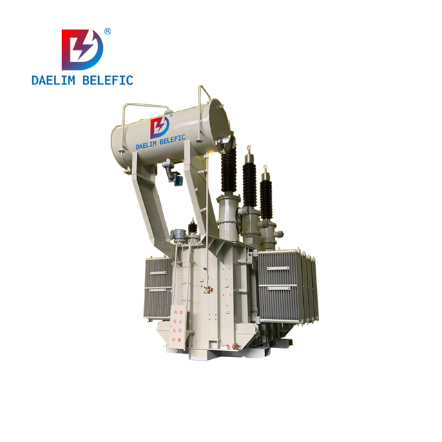
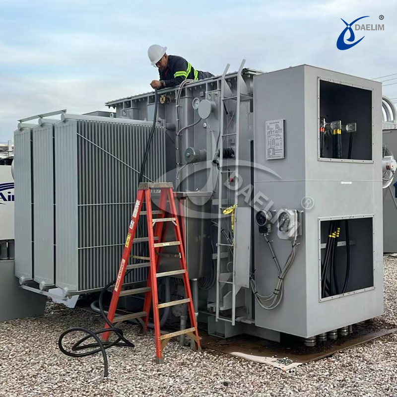
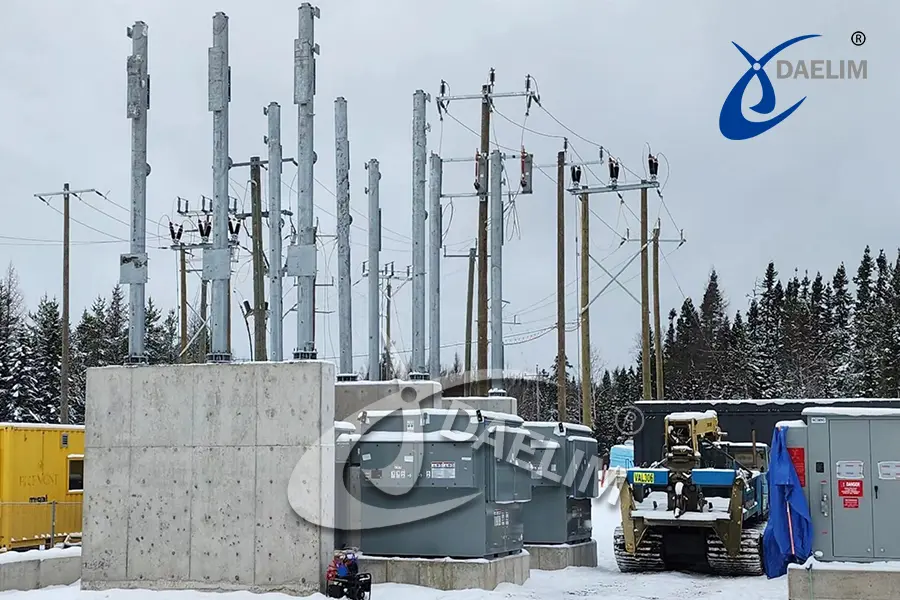
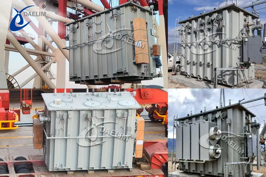
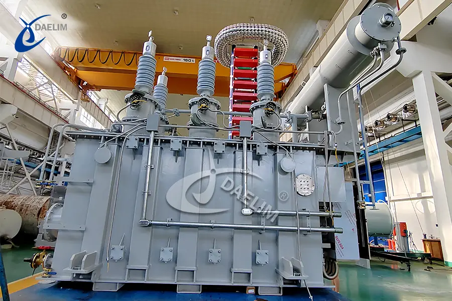
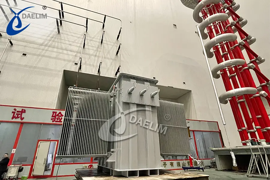
132 kV 75 MVA Transformer
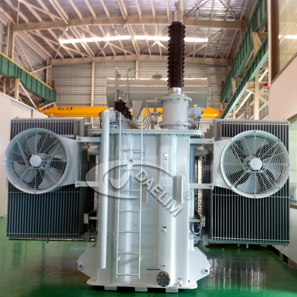

- Primary Voltage Ratings: 132 kV
- Secondary Voltage Ratings: 33kV
- TYPE: 3 PH Oil Transformer
- Standards: IEC,EN
- Power Rating: 75 MVA
- Cooling Method: ONAN/ONAF
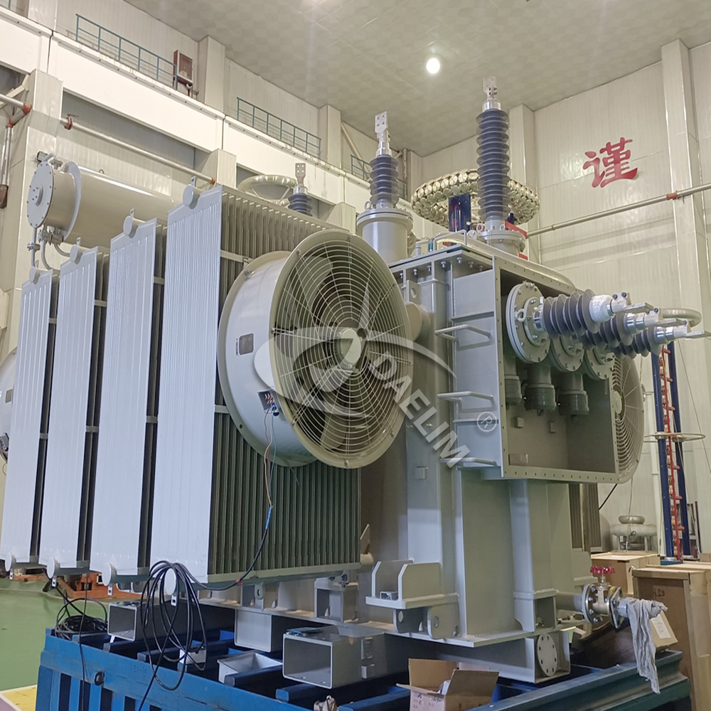
The 132 kV, 75 MVA transformer is designed for three-phase systems at 50 Hz, withstanding short circuits up to 2 seconds without damage. It features a ±5% tap changer on the HV side, IP55 protection, and forced oil-air cooling. Key accessories include a conservator with magnetic oil level indicators, a Buchholz relay, and various temperature and oil gauges. The transformer undergoes rigorous type and routine tests, including lightning impulse and short-circuit tests, ensuring reliable performance.
Quote Now
General Description
The 132 kV, 75 MVA transformer is designed for use in three-phase power systems operating at 50 Hz. This transformer can endure the thermal and mechanical effects of a maximum short circuit at its terminals for up to 2 seconds without sustaining permanent damage, while maintaining winding temperatures below the permissible maximum of 250°C across any tapping position.
Tap Changer
The transformer is equipped with a tap changer installed on the high-voltage (HV) side. It features five steps, allowing voltage adjustment within a ±5% range in 2x2.5% fully rated steps both above and below the nominal primary voltage.
Accessory Features
-
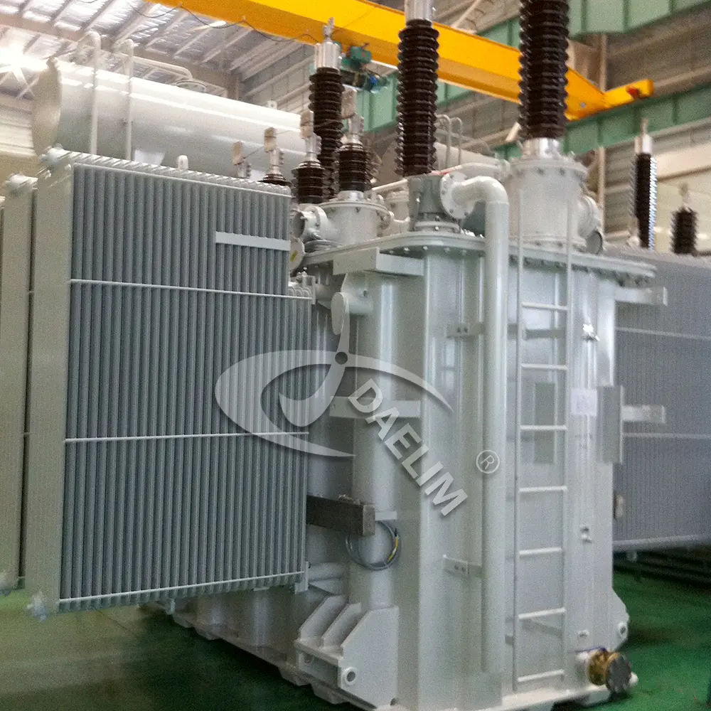
Aluminum Ladder: A suitable aluminum ladder is provided for easy access to the top of the transformer.
Enclosure and Protection
-
Ingress Protection (IP Rating): The transformer enclosure has an IP55 rating, ensuring protection against dust and water ingress.
Cooling System
-
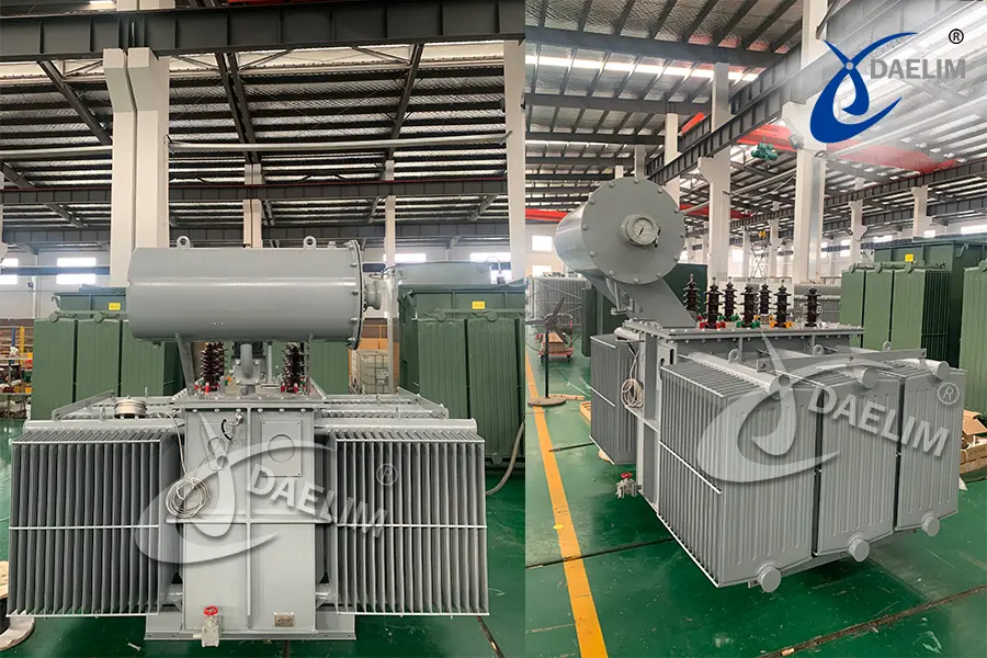
Forced Air Cooling: The transformer utilizes an oil-based cooling system complemented by forced air cooling. The radiators are hot-dip galvanized to prevent rust and corrosion. They are designed to withstand the vacuum and pressure conditions specified for the main tank, are easy to clean and paint, and prevent water accumulation. Radiators are detachable and bolted to the tank using welded steel flanges with oil-tight gaskets. Each radiator connection includes a shut-off valve with locking capabilities.
Bushings
-
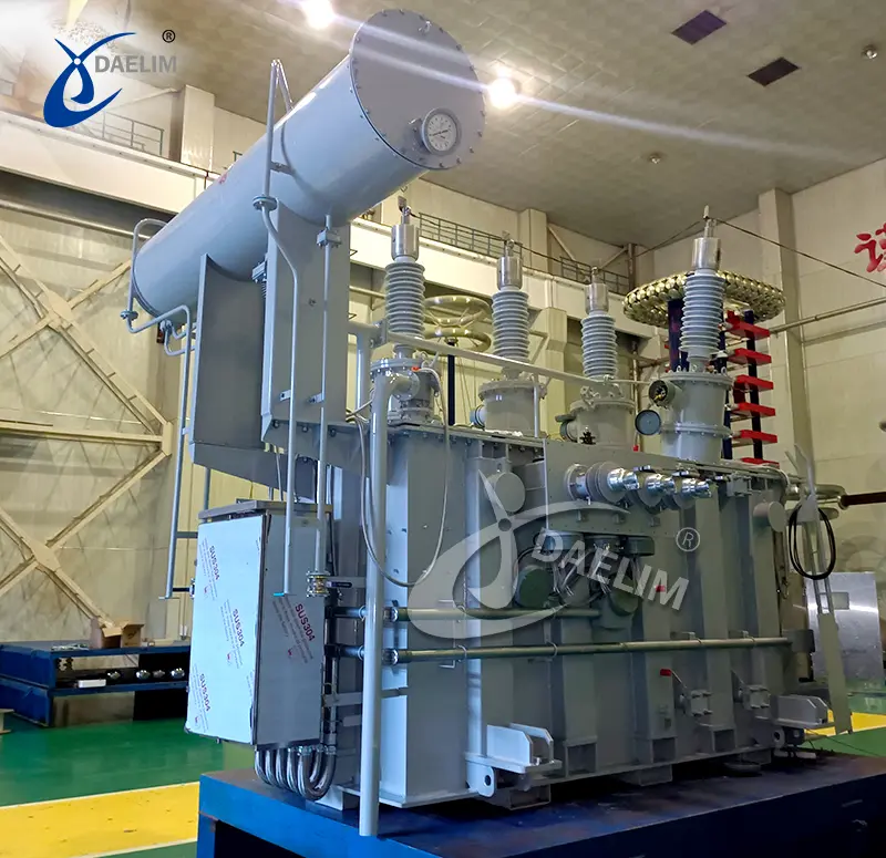
The transformer is equipped with high-voltage, low-voltage, and neutral bushings, compliant with IEC Standard 60137.
On-Load Tap Changer
-
The transformer is fitted with an On-Load Tap Changer (OLTC) for efficient voltage regulation.
Accessories
-
Conservator: Includes a magnetic oil level indicator on either side, with a range of -20°C to +100°C and contacts for alarm at various levels. The conservator also features a breather and dryer device.
-
Gas and Oil Actuated Relay (Twin Float Buchholz Relay): Equipped with two contact sets—one for slow gas accumulation alarm and one for surge oil and gas accumulation to trip the transformer. Positioned for optimal viewing of the sight glass without de-energizing the transformer.
-
Oil Level Gauge: A magnetic oil level gauge, readable from ground level, with indicators for minimum, maximum, and normal oil levels. Includes contacts for low oil level alarm.
-
Winding Temperature Indicator: A dial-type indicator per winding, responsive to top oil temperature and winding current, calibrated to monitor the hottest spot temperature. Includes adjustable contacts for cooling control, alarm operation, and load-breaker tripping.
-
Oil Temperature Indicator: Dial-type, located in the path of the hottest oil, with adjustable alarm contacts for monitoring.
-
Pressure Relief Device: Equipped with semaphore and alarm contacts for visual and electrical pressure indication. Sized for rapid pressure release above set values.
-
Silica Gel Breather: Designed for desiccant agents with a grain size of at least 2.5 mm. Located at a convenient height and maintenance-free.
Control and Signal Wiring
-
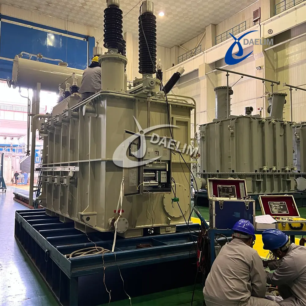
Marshalling Box & Cooler Control Panel: All control and signal wiring is housed in a weatherproof, centrally located terminal cabinet, equipped with a hinged cover, threaded conduit connections, and marked terminal blocks. Includes ample spare terminals for various leads and connections.
Type Tests
-
Lightning impulse test
-
Short-circuit test
-
Measurement of harmonics on no-load current
-
Noise level test
Routine Tests
-
Impedance voltage test at normal maximum and minimum tapping positions
-
No-load test with 400V applied to HV terminals
-
Magnetic circuit insulation test with 2 kV for 1 minute
-
No-load current and loss measurements at various voltages (70%, 80%, 90%, 100%, 110%, and maximum system voltage)
-
Magnetic balance test
Related Products
Related Article


