How To Do Transformer Coil Winding Calculation
Electric transformers work to control the electricity by irregulating the electric voltage and current that moves out of these machines. These electrical machines are very simple looking electrical devices and have only 3 to 4 major parts that work together to deliver the required out.
Transformer coil winding is one of those major parts that work to either step up or step down the provided electrical voltage. Whether the electrical transformer winding will step up or step down the provided voltage and how much it will step or step down the provided voltage depends on the design and calculation made during the designing stage.
Now if you are wondering how to do Transformer coil winding calculations or you're looking for the Transformers step up formula or how to calculate Transformer voltage. Then this article is for you, we have developed a very comprehensive guide on how to do Transformer coil winding calculations.
We will introduce you to all the basic terminologies and basic formulas and will provide you with a simple calculation as a sample.
Contact Daelim TransformerBasics of Transformer Coil Winding
 Before we go into the calculation of Transformer coil winding, it is important for you to know the basics associated with the Transformer coil winding calculation.
Transformer consists of two different types of winding, one is called primary winding and the other one is called secondary winding. Primary one winding is one that receives the input voltage and the secondary winding is one that delivers the output voltage.
Along with the winding type you need to know:
- The value of input voltage
- The required output voltage required from the transformer
- You also need to know the operating frequency of alternating current
- The current carrying capacity of the wire from which the Transformer winding will be made
- You also have to know the material from which the Transformer core will be made
You may enjoy: Why does transformer require a balanced winding?
Key Formulas and Parameters for Coil Winding Calculation
Perform proper calculation for transformer winding you need to know the transformer formulas and Transformer equations that will be used in calculation.
Turn Ratio calculation
Doing calculations for transformer turn ratio is the first step in doing transformer coil winding calculation. It is this ratio that determines whether the transformer is a step up Transformer or is a step down transformer. This ratio also defines the voltage that you can draw from Transformer winding.
Transformer turn ratio formula
N1 / N2 = V1 / V2
Now in the above formula the N1 and N2 represent the number of terms in the primary winding and the number of terms in the secondary winding of Transformer respectively. In very similar manner the V1 and V2 represent the voltage in primary winding and the voltage in the secondary warning of the transformer respectively.
Turn per volt calculation
Turn per volt is a term used to represent the number of terms in transformer winding that is needed to control just one volt of electricity. This will in return find the number of totals turned in the Transformer primary winding and Transformer secondary winding.
The number of old depends upon the Transformer core material and its size. It can be calculated using following transformer formula
Turns per volt (TPV) = 3615.84 / area (mm²)
Area of the transformer Core
Transformer winding will be made on the Transformer Core. Area of the transformer core will define the number of terms per Hold and will have early influence on the number of turns and the wire gauge required. The area of the transformer core itself depends upon the electrical power the transformer has to control. the area of the transformer core can be calculated using following Transformer equation
Core Area in mm² = ²√Watts * 116.129323
Reading more: Why Choose Silicon Steel Sheets for Transformer Cores?
Total number of turns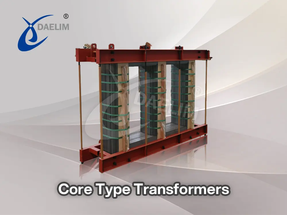
According to the working principle of the transformer, the number of turns in the primary and secondary voltage define whether the transformer is a step up or a step down transformer. You need to know the turn per volt value and total voltage applied to the winding to calculate the number of turns needed in the winding. It can be calculated using the following formula.
N = TPV * V
In the above equation N represents the number of turns in either primary or secondary winding, TPV represents the term per volt value of the transformer and we represent the voltage applied to the specific winding.
Core area and magnetic flux density
You can calculate the magnetic flux density of the transformer core using the voltage provided by the frequency of the voltage, the coal area and the number of terms of the winding. Following is the Transformer formula for calculating in magnetic flux density transformer.
B = V4.44 * f * A * N
In the above equation the be represents in the magnetic flux density of the transformer Core it is Measured by the unit Tesla. Veer presents the voltage applied to the winding and represents the frequency of that voltage. The A represents the area of the core in metre square and and represents the number of terms of the winding.
Wire gauge selection
In transformer winding it is highly important to measure the exact diameter of the wire also called the wire gauge. For the Transformer winding the wire gauge used in the winding depends on the current and the current density. The current density is the current per millimetres square.
Following equation can be used to measure the cross section area of the wire. We can measure the exact diameter and select the appropriate wire gauge for the Transformer winding wire.
A = I / J
A represents the cross section area of the wire, I represents the current in ampere, and J represents the current density in ampere per millimetre square.
Reading more about Transformer Gauges
Step by Step Guide for Coil Winding Calculation
 Now based on the Transformer formula and Transformer equation we have presented above, we will show you how to do step by step calculation of your transformer winding.
Step one define the Transformer specification
The first tab in designing any transformer winding is the determination of the specifications against which the Transformer will be designed. These specifications include the primary voltage that will be supplied into the Transformer through primary winding, the secondary voltage that will be drawn out of the Transformer as output from secondary winding, the load current and the operating frequency of the alternating current. To show you a sample calculation, we will present you with a 220v to 12v transformer winding formula.
- Primary voltage = 220V AC
- Secondary voltage = 12V AC
- Load current = 5A
- Operating frequency = 50Hz
Step 2 calculate the turn ratio
The first calculation that we will perform will be the calculation of the turn ratio. The primary and the secondary voltage provided in these calculations will be the V1 and the V2 respectively.
N1 / N2 = V1 / V2
N1 / N2 =220 / 12
N1 / N2 = 18.33
Above calculation means that the number of terms in the primary winding will be 18.33 times more than the terms present in the second winding. so it is a simple step down Transformer that reduces the voltage from 220 volts to 12 volts.
Step 3 find the core area needed
It is important to find the Transformer core areas needed to support the power transfer as this area will be used in further calculations to find the total number of turns and also to find the magnetic flux density of the core.
Core Area in mm² = ²√Watts * 116.129323
Core Area in mm² = ²√60 * 116.129323
Core Area in mm² = 899.5 = 900
The power of the transformer remains the same for the input and output so it doesn't matter from which side voltage and current you use to get Transformer power. In our case if we multiply the output volts of 12 volts with the load current of 5 amperes, then we have the power of 60 watts for this transformer.
Step 4 find the turn per volt for the winding
Calculating the term for what will give you returns of primary and then the terms of secondary winding that are needed to control or regulate just one volt of electric current. It totally depends on the area of the transformer core that we have calculated just above.
Turns per volt for 50 Hz = 3615.84 / area (mm²)
Turns per volt for 50 Hz = 3615.84 / 900 (mm²)
Turns per volt for 50 Hz = 4.0
So with the given Transformer core area we have a turn per volve value of 4 for deal alternating current of 50 Hz.
You may enjoy: How To Check Transformer Primary And Secondary?
Step 5 determine the number of Turn
Now we can use the turn per volt and the voltage of primary and secondary winding to calculate the total number of turns that we need in primary and secondary transformer winding to get the required step down feature from our transformer.
So the total number of terms in primary winding can be calculated as
N1 = TPV * V
N1 = 4 * 220
N1 = 880
Similarly we can also measure the number of terms in the secondary warning of the transformer
N2 = TPV * V
N2 = 4 * 12
N2 = 48
Now here we can also check whether the number of turns in the primary winding and secondary winding satisfies the turn ratio we have calculated in the very first steps. As initially we have measured the term ratio N1/N2 is equals to 18.33, So
N1 / N2 = 18.33
880 /48 = 18.33
18.33= 18.33
As we have obtained, the left hand side equals the right hand side so now we can say that your calculations of total number of turns in primary and secondary warning of the Transformer satisfies the term ratio we have calculated initially based on the voltage provided and required by the transformer.
Step 6 Measure the wire gauge
In the last step we will measure the size of the wire which will be used to make the Transformer primary and secondary winding. The wire size of the primary and secondary will be different as both process different quantities of the electric current.
Measuring wire size for primary winding
I = P/V
In the above equation
I = current in the primary winding
P = power of the Transformer
V = voltage applied
I = 60/220
I = 0.27 A
Considering the standard current density of 3 ampere per millimetre square we can measure the wire size in mm square from the current value calculated about.
Size in mm square = Current / Current Density
Size in mm square = 0.27 / 3
Size in mm square = 0.09
Measuring wire size 4 secondary winding
I = P/V
I = 60/12
I = 5 A
Size in mm square = Current / Current Density
Size in mm square = 5 / 3
Size in mm square = 1.7
Selecting appropriate wire gauges:
- Primary wire: SWG 34 (~0.09 mm²)
- Secondary wire: SWG 14 (~1.7 mm²)
Conclusion
Transformers are very efficient and precisely designed electrical devices. If you are in the process of designing a transformer then you have to go through the Transformer coil winding calculations. The Transformer coil winding calculation depends on the primary winding voltage, secondary winding voltage, the voltage frequency, and the load charge current. During the Transformer designing process you need to calculate the turn ratio, The Transformer core area, the value of turn per volt, any total number of turns in primary winding and secondary winding. You also need to calculate the wire gauge from which the primary and the secondary winding will be made.
Follow Up
Transformer is a complex process, you need to go through various details, information, and specifications and need to perform serial calculations that will define the transformer winding and core specification. We at Daelim design and develop transformers of all types, sizes and load capacity by following the highest international standards.

If you have any questions related to Transformer coil winding calculation then you can Contact Us and our team of designers will talk you through the process.
Related Products

Related Article
Choosing the Right Transformer Enclosure for Your Project
Selecting the right transformer enclosure ensures safety, durability, and optimal performance. This guide explores different NEMA-rated enclosures, their materials, and protective features against environmental hazards like dust, moisture, and corrosion. Whether for indoor or outdoor applications, choosing the proper enclosure safeguards transformers, extends their lifespan, and reduces maintenance costs. Understand key factors like protection levels, material selection, and environmental conditions to make an informed decision. Contact Daelim Transformer for expert guidance in finding the best enclosure for your needs.
All You Need To Know About Traction transformer
Traction transformers are essential for powering electric trains, trams, and buses by stepping down high voltage to safe levels. Designed for harsh conditions, they offer energy efficiency, reliability, and compactness. Used in railways and industrial systems, they face challenges like thermal stress and space limits. Advanced materials and smart tech enhance their performance and durability.
Construction and Working of Single Phase Transformer
Single phase transformers are widely used in residential areas to step voltage up or down using one live and one neutral wire. They consist of core, windings, insulation, cooling systems, and protective tanks. Working on Faraday’s Law, they convert AC voltage efficiently. Construction varies by type, using copper/aluminum windings and either dry or oil cooling systems.
How To Calculate Transformer Load Capacity?
This article explains how to calculate transformer load capacity, detailing key concepts, step-by-step methods, and factors like efficiency, temperature, and load type. It highlights the importance of accurate calculations for safety and performance. Software tools like ETAP and SKM Power Tools are recommended. Daelim Transformer offers expert support and high-quality transformers for global clients.
500 kVA Distribution Transformer for the Greek Market
Today, we're thrilled to showcase a European transformer project tailored for the Greek market. This project involves the supply of 500 kVA distribution transformers, with an input voltage of 20 kV and an output voltage of 400V. The client has requested adherence to both IEC and TIER-II energy efficiency standards. With a total quantity of 5 units, this project marks another milestone in Daelim Transformer's commitment to delivering high-quality solutions worldwide.
2600 kVA Pad Mounted Transformer for Cryptocurrency Mining
Daelim Transformer successfully provided three customized 2600 kVA pad mounted transformers to power a state-of-the-art cryptocurrency mining facility in Texas, USA. Our transformers were meticulously designed to meet the unique demands of the mining operation, ensuring seamless power distribution with unwavering reliability and efficiency.